
A process unit needs to cool a hot product stream before storage. The utility water is available, the target outlet temperature is known, and the first instinct is often to ask for a heat exchanger size.
But the more important question comes first: which exchanger construction fits the fluids, operating conditions, maintenance practices, and future operating changes? A shell-and-tube exchanger and a plate heat exchanger can both perform the same thermal duty, yet they do not respond to real plant conditions in the same way.
Choosing poorly can mean excess pumping power, rapid fouling, difficult cleaning, leakage concerns, limited capacity, or an exchanger that is physically larger than the space allows. Choosing well creates a dependable part of the process rather than a recurring bottleneck.
This comparison gives students and working engineers a practical framework for selecting between two of the most widely used exchanger families. 🧪
🔍 1. Start with the Real Selection Question
Neither design is universally better. The correct choice depends on the whole duty, not simply on which exchanger has the highest heat-transfer coefficient.
A useful question is: can this exchanger deliver the required duty safely, cleanly, economically, and reliably over its expected operating life?
That question includes thermal design, pressure drop, mechanical limits, fluid cleanliness, inspection access, and plant operating philosophy.
🌡️ 2. What Both Exchangers Do
Both devices transfer thermal energy from a hotter fluid to a colder fluid through a separating metal wall. Under normal operation, the two process streams do not mix.
The basic heat-duty relationship is:
Q = U × A × ΔTlm
Here, Q is heat duty, U is overall heat-transfer coefficient, A is heat-transfer area, and ΔTlm is the log-mean temperature difference, often adjusted by a correction factor for some flow arrangements.
Different exchanger constructions influence every term except the required duty itself.
🧱 3. Shell-and-Tube Construction
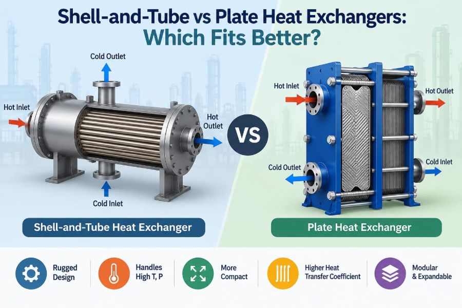
A shell-and-tube exchanger contains a bundle of many tubes inside a cylindrical shell. One fluid flows through the tube side, while the other flows over the outside of the tubes within the shell.
Tube sheets hold the tubes, channel heads distribute tube-side flow, and baffles guide shell-side flow across the bundle. Mechanical details vary substantially among fixed-tubesheet, U-tube, and floating-head arrangements.
This construction is robust, familiar, and available in a very broad range of sizes and materials.
🥪 4. Plate Heat Exchanger Construction
A plate heat exchanger uses a stack of thin, corrugated metal plates. Alternating channels carry the hot and cold fluids, so each plate separates the two streams.
Corrugations create turbulence and support the plates against pressure. In a gasketed design, gaskets seal the channels and direct fluid to the proper passages.
Other plate-based constructions exist, including brazed, welded, and semi-welded units. Their allowable pressures, cleaning options, and service suitability differ, so “plate exchanger” is not a single mechanical category.
🌀 5. Flow Pattern Changes Performance
Plate exchangers commonly approach true countercurrent flow. The hot and cold streams move in opposite directions through adjacent channels, maintaining a favorable temperature-driving force along much of the flow path.
Shell-and-tube exchangers can also use countercurrent tendencies, especially with multiple passes, but shell-side flow is more complex because baffles redirect it across the tube bundle.
Flow arrangement affects temperature approach, exchanger area, and the need for temperature-correction factors.
📏 6. Temperature Approach Is a Major Divider
A close temperature approach means the outlet temperature of one stream comes near the outlet temperature of the other stream. This often demands a large effective driving force and favorable flow arrangement.
Plate exchangers are frequently attractive for close approaches because of their near-countercurrent channel arrangement and high heat-transfer performance. This can reduce the area needed for a given duty.
That advantage must still be checked against fouling, pressure limits, and the temperature program. A close approach alone does not select the equipment.
⚡ 7. Why Plate Units Often Have High U Values
Plate channels are narrow and corrugated. At suitable flow rates, this geometry promotes mixing and disrupts the thermal boundary layer near the plate surface.
Thin plates also provide low wall resistance. Together, these features can produce high overall heat-transfer coefficients for clean, compatible fluids.
However, high turbulence has a cost: pressure drop can rise quickly. The designer must balance thermal intensity against available pumping or compression energy.
🧰 8. Why Shell-and-Tube Units Remain Essential
Shell-and-tube exchangers are often preferred where operating pressure or temperature is demanding, where a very large duty is required, or where mechanical ruggedness is central to the service.
They can accommodate long tubes, large shell diameters, multiple shells, and specialized mechanical arrangements. They are also well established in many industrial maintenance programs.
Their larger size for a comparable clean-fluid duty is not automatically a disadvantage when durability and serviceability dominate the decision.
🧪 9. Put the Right Fluid on the Right Side
For a shell-and-tube exchanger, fluid allocation is a key design choice. The higher-pressure fluid is often placed in the tube side because the tube-side pressure boundary is usually more economical to contain.
Corrosive fluid may go through tubes when expensive corrosion-resistant material can then be limited to tubes, tube sheets, and related wetted parts. Conversely, a fluid needing mechanical shell-side cleaning may favor shell-side placement.
In plate exchangers, both streams use similar channel geometry, so allocation is influenced more by pressure drop, fouling tendency, corrosion, gasket compatibility, and cleaning strategy.
🧹 10. Fouling Can Overrule Thermal Superiority
Fouling is the accumulation of unwanted material on heat-transfer surfaces. It may result from scale, corrosion products, suspended solids, biological growth, polymer deposits, coking, or crystallization.
A compact plate exchanger can lose performance rapidly if narrow channels become restricted. A shell-and-tube exchanger may tolerate certain dirty services better, particularly when it offers larger flow passages or practical mechanical cleaning.
Selection should use the expected operating fluid condition, not the clean sample seen during commissioning.
🪥 11. Cleaning Methods Shape the Choice
Gasketed plate exchangers can be opened, separated, inspected, and manually cleaned when the frame and plant layout permit it. They can also be cleaned in place when deposits are soluble and a suitable cleaning procedure is available.
Straight-tube shell-and-tube exchangers can allow mechanical tube cleaning from the channel ends. This is valuable for water-side scale and deposits that resist chemical cleaning.
U-tube bundles avoid one tube-sheet joint and accommodate thermal expansion well, but the bend region can be difficult or impossible to mechanically clean with conventional straight tools.
🧫 12. Viscous Fluids Need Special Attention
High-viscosity fluids develop thicker velocity and thermal boundary layers, reducing heat transfer. They also produce larger pressure losses for a given flow path.
Plate corrugations can generate strong mixing and may perform very effectively with some viscous liquids. Yet a highly viscous, sticky, or shear-sensitive product may plug channels or create unacceptable pressure drop.
Shell-and-tube designs can offer larger passages and tailored shell-side arrangements, but their thermal performance with viscous fluid must be evaluated carefully rather than assumed.
🧊 13. Phase Change Is Not Just Another Duty
Condensation and boiling involve latent heat, vapor distribution, drainage, pressure drop, and sometimes noncondensable gases. They require service-specific design, not just a sensible-heat calculation.
Shell-and-tube exchangers are widely used as condensers, reboilers, and vaporizers because their geometry can be adapted to vapor-liquid behavior and large vapor volumes.
Plate exchangers can also serve phase-change duties, especially in suitable refrigeration and process applications, but distribution, pressure limits, and manufacturer guidance become especially important.
🛢️ 14. Pressure and Temperature Limits Matter
All exchanger designs have pressure and temperature limits set by their construction, materials, joints, seals, and applicable design requirements. The process design pressure and temperature must include credible operating and upset conditions.
Gasketed plate units may be limited by gasket material, gasket retention, and frame design. Welded or brazed plate designs avoid conventional gaskets but introduce different inspection and repair considerations.
Shell-and-tube exchangers are commonly selected for severe pressure-temperature combinations because their pressure boundaries can be designed with substantial mechanical strength.
🧯 15. Think About Thermal Expansion
A large temperature difference can make the shell and tubes expand by different amounts. If this differential movement is restrained, thermal stresses can become significant.
U-tube and floating-head shell-and-tube arrangements allow relative movement between tubes and shell. Fixed-tubesheet designs may need a shell expansion joint or may suit services with manageable differential expansion.
Plate packs also expand, but their compact geometry and construction create a different mechanical problem. The full temperature cycle, not merely the normal operating point, should be reviewed.
💧 16. Pressure Drop Is an Operating Cost
Pressure drop represents energy that pumps or compressors must supply. A design with excellent heat transfer may be a poor choice if it consumes an unacceptable share of the available pressure budget.
Plate exchangers often use narrow channels and turbulent flow, making pressure-drop control central to their sizing. Adding channels can reduce velocity and pressure loss, although it changes thermal performance and equipment size.
Shell-and-tube designs also require pressure-drop checks on both sides. Baffle spacing, tube passes, tube diameter, and shell-side geometry all influence the result.
📊 17. A Direct Comparison
| Selection factor | Shell-and-tube tendency | Plate exchanger tendency |
|---|---|---|
| Clean-liquid heat transfer | Moderate to high, depending on design | Often high because of corrugated channels |
| Footprint for a given duty | Often larger | Often smaller and more compact |
| Very high pressure or temperature | Commonly strong choice | Depends strongly on plate construction |
| Mechanical cleaning | Good for accessible straight tubes | Good for openable gasketed plate packs |
| Dirty or fibrous streams | Often more tolerant with suitable geometry | Channel plugging can be a concern |
| Capacity expansion | May require a new bundle or exchanger | Gasketed units may allow added plates within frame limits |
These are tendencies, not guarantees. A specific exchanger model, fluid, and operating window can reverse an apparent general advantage.
🔩 18. Materials Compatibility Is More Than Metal Choice
Heat-transfer surfaces must resist corrosion, erosion, and chemical attack from both fluids and from cleaning chemicals. Material selection may involve carbon steel, stainless steels, nickel alloys, titanium, or other suitable materials.
For gasketed plates, the gasket is also a wetted material. Its compatibility with temperature, chemicals, oils, oxidizing agents, and cleaning fluids is as important as plate-alloy selection.
Do not treat a corrosion-resistant plate as proof that the complete exchanger is chemically suitable.
🧭 19. Leakage Risk Has Different Forms
Every exchanger has potential leak paths. In shell-and-tube equipment, tube leaks can allow one process stream to contaminate the other, while gasketed joints and channel connections are additional external leak locations.
In gasketed plate exchangers, plate gaskets create many sealed interfaces. Proper assembly, compression, gasket condition, and operating limits are therefore important.
Where cross-contamination has severe consequences, engineers should consider detection, pressure relationships, double-wall concepts where appropriate, and the consequences of both internal and external leakage.
🔧 20. Maintenance Means Access, Not Just Repairability
A shell-and-tube exchanger may require bundle pulling space, lifting access, and sufficient room to remove channel covers. These layout requirements can be substantial.
A plate exchanger needs space to open the frame and remove plates for inspection. It may have a much smaller footprint, but the service corridor in front of the frame still matters.
Ask maintenance personnel how the unit will actually be isolated, drained, opened, cleaned, tested, and returned to service.
➕ 21. Future Capacity Can Favor Plates
Many gasketed plate exchangers can be expanded by adding plates, provided the frame, tie bolts, connections, pressure rating, and hydraulic limits permit it. This can make them attractive where moderate future growth is credible.
Expansion is not limitless. Added plates alter channel velocity, pressure drop, and thermal performance, and may require a design review.
Shell-and-tube capacity changes may require a replacement bundle, a new exchanger, or parallel equipment. In some plants, that is entirely acceptable because future additions are already planned in parallel trains.
🏗️ 22. Layout and Installation Affect Total Cost
A plate exchanger can reduce floor area and structural load because it is compact. This is valuable in constrained revamps, skid-mounted systems, and buildings with limited equipment space.
A shell-and-tube unit may be easier to integrate horizontally on pipe racks or vertically in thermosiphon-related duties. Its orientation can be part of the process design rather than merely a layout preference.
Include valves, strainers, vents, drains, bypasses, insulation, lifting routes, and cleaning connections when comparing installed equipment.
🧰 23. Strainers Are Not a Substitute for Fluid Control
Upstream strainers can protect plate channels from debris and can help protect small passages in other exchanger types. They add pressure drop and require a cleaning plan of their own.
A strainer will not prevent dissolved salts from scaling, unstable fluids from polymerizing, or biological growth from developing. It is one layer of protection, not a complete fouling solution.
Good selection combines pretreatment, velocity control, temperature management, monitoring, and practical cleaning.
📈 24. Design for Off-Design Operation
Plants rarely operate forever at one flow rate and one inlet temperature. Seasonal utility temperatures, turndown, debottlenecking, batch campaigns, and feed changes all shift exchanger behavior.
At low flow, a plate exchanger may lose turbulence and heat-transfer performance. At high flow, its pressure drop may become limiting. Shell-and-tube equipment also changes behavior as tube-side and shell-side velocities move away from design.
Review expected minimum, normal, and maximum cases instead of approving a unit based only on one nominal point.
🧮 25. Use Thermal Design and Mechanical Design Together
Thermal sizing estimates the required area and predicts outlet temperatures, pressure drops, and fouling effects. Mechanical design then establishes whether the proposed construction can safely contain pressure, tolerate temperature, and withstand loads.
These tasks are connected. Changing plate type, tube diameter, number of passes, baffle arrangement, or channel count alters both thermal-hydraulic and mechanical behavior.
A reliable specification states the process conditions clearly and leaves enough information for vendors or internal designers to select a feasible construction.
📝 26. Build a Better Datasheet
An exchanger datasheet should communicate more than flow and temperature. Missing details often cause unsuitable selections or late redesign.
- Fluid composition, phase, solids content, viscosity, and fouling tendency
- Flow rates for normal, minimum, maximum, and startup cases
- Inlet and required outlet temperatures
- Operating and design pressures and temperatures on both sides
- Allowable pressure drop, corrosion concerns, and materials restrictions
- Cleaning method, inspection requirements, and plot-space constraints
- Consequences of internal leakage and future capacity expectations
Clear process information is more valuable than an early preference for a particular exchanger type.
🚫 27. Avoid These Common Shortcuts
Do not select a plate exchanger solely because it is compact, or a shell-and-tube exchanger solely because it looks more rugged. Both shortcuts ignore the service.
Also avoid using a single generic fouling factor without understanding the deposit mechanism. Fouling behavior can dominate long-term performance.
Finally, do not accept a pressure-drop result without considering the pump curve, control-valve authority, and the process consequences of reduced flow.
✅ 28. A Practical Selection Sequence
First define the duty and calculate a preliminary temperature program. Identify whether sensible heating/cooling, condensation, boiling, or a mixed duty is involved.
- Screen pressure, temperature, fluid compatibility, and contamination risk.
- Set realistic allowable pressure drops and cleaning requirements.
- Evaluate shell-and-tube and suitable plate constructions for thermal and hydraulic performance.
- Check mechanical feasibility, layout, maintenance access, and isolation needs.
- Compare lifecycle implications, including fouling, pumping energy, downtime, and likely expansion.
- Review credible upset cases and cross-contamination consequences before finalizing.
This sequence makes the decision traceable and easier to defend during design review.
⚖️ 29. The Core Principle: Fit the Construction to the Service
Plate heat exchangers often excel when fluids are relatively clean, compactness matters, close temperature approaches are needed, and pressure-temperature limits are compatible with the selected construction.
Shell-and-tube exchangers often excel in demanding pressure-temperature service, large duties, phase-change applications, and services where geometry and maintenance practices favor a robust tubular design.
The best exchanger is not the one with the most impressive isolated feature; it is the one whose thermal, hydraulic, mechanical, and maintenance behavior matches the actual process.
Make the choice from the full operating story, then verify it with sound thermal and mechanical design. That is how a heat exchanger becomes a reliable process asset rather than a persistent constraint. ⚖️🌡️🔧