
A batch is running smoothly until the level in a vessel seems to rise far faster than expected. Sight glasses turn white, a separator begins carrying liquid overhead, and an operator has to decide whether the problem is a bad level reading, a process upset, or simply foam.
Foam can look harmless: a layer of bubbles on a liquid surface. In an industrial unit, however, it can distort measurements, reduce capacity, contaminate downstream equipment, and turn routine control into an unstable exercise.
The challenge is that foam is not one single problem. It is the visible result of gas dispersion, liquid chemistry, solids, temperature, pressure, equipment geometry, and operating conditions interacting at once.
Good foam control starts with understanding what the bubbles are doing, why they survive, and which intervention addresses the actual mechanism rather than just suppressing the symptom.
🫧 What Foam Is in Process Equipment
Foam is a dispersion of gas bubbles separated by thin liquid films. It forms when gas enters or is generated in a liquid and the bubbles do not quickly merge, rise, and break at the surface.
A small amount of transient froth may be normal in an aerated tank or during filling. Industrial concern begins when the foam is stable enough to accumulate, occupy useful vessel volume, interfere with separation, or leave the equipment through a vent or outlet.
Foam should not be confused with ordinary bubbles. A bubble is an individual gas pocket; foam is a structured population of bubbles whose liquid films are stabilized by the properties of the surrounding liquid.
🔬 The Thin Films That Keep Bubbles Alive
For foam to persist, the liquid film between adjacent bubbles must resist drainage and rupture. Pure liquids often form relatively unstable bubbles, while many real process streams contain components that make bubble films more durable.
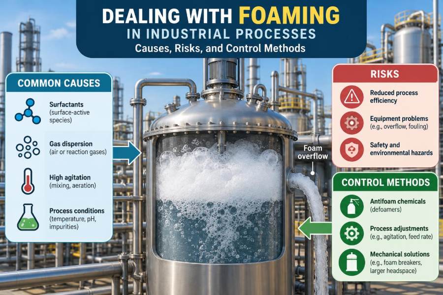
Surface-active molecules, often called surfactants, collect at the gas-liquid interface. Their presence can lower surface tension and create an interfacial layer that slows bubble coalescence, the merging of two or more bubbles into a larger one.
Viscosity matters too. A more viscous liquid drains more slowly from bubble films, giving the foam longer to survive. Suspended solids, polymers, proteins, oils, salts, and reaction products may either stabilize or destabilize foam depending on their chemistry and concentration.
🌬️ How Gas Gets Into the Liquid
Many units deliberately disperse gas: fermenters require oxygen, flotation systems use bubbles for separation, and hydrogenation reactors depend on gas-liquid contact. In these systems, foam management is part of normal design and operation.
Elsewhere, gas entry is unintended. A leaking pump seal, a vortex at a tank outlet, an open suction line, or a poorly submerged return line can entrain air. A pressure drop can also release dissolved gas from a liquid, much like carbonation escaping when a bottle is opened.
Rapid mixing, spray impact, pumping through restrictive valves, and liquid cascading into a vessel all create fresh interfacial area. If the fluid has foam-stabilizing components, these mechanical actions can convert a minor aeration issue into persistent foam.
⚗️ Surfactants and Contaminants as Hidden Triggers
Detergents and cleaning residues are familiar foam promoters, but they are not the only ones. Process additives, corrosion inhibitors, lubricants, extraction chemicals, natural organic matter, and traces of product can change foaming behavior dramatically.
A common troubleshooting trap is to focus only on the main feed specification. Low-level contaminants entering with wash water, recycled streams, condensate, or cleaning rinse can be enough to alter surface behavior.
The effect is not always linear. A small concentration change may have little visible consequence until an operating condition, such as higher agitation or gas rate, crosses a threshold and exposes the stream’s foaming tendency.
🧱 The Role of Solids, Particles, and Emulsions
Fine solids can stabilize foam by becoming trapped at the gas-liquid interface. This is sometimes called particle-stabilized or Pickering foam. The particles form a physical barrier around bubbles and make film rupture more difficult.
Biomass in fermentation broth, catalyst fines, clays, pigments, and precipitated salts can all contribute. Their particle size, wettability, concentration, and interaction with dissolved organics influence whether they promote foam.
Emulsified oil creates another complication. Some oils break foam, while others, especially when stabilized as fine droplets with surfactants, can support stubborn mixed foams. That is why a simple statement such as “oil suppresses foam” is unreliable in a complex process stream.
🌡️ Temperature, Pressure, and Composition Changes
Foam behavior can shift during a run even when the equipment settings appear unchanged. Temperature affects viscosity, surface tension, vapor pressure, and gas solubility, so heating or cooling can alter both bubble generation and bubble stability.
Lowering pressure may cause dissolved gases or volatile components to flash, producing vigorous bubbling. In evaporators, flash drums, distillation equipment, and vacuum systems, this can generate foamy vapor-liquid mixtures rather than a clean phase split.
Composition often changes over time during reactions, concentration steps, and biological growth. A system that operated quietly at the start of a batch may become foam-prone once products, impurities, or solids reach a critical range.
🔄 Agitation and Shear: Useful but Sometimes Excessive
Agitators are designed to blend, suspend solids, transfer heat, and disperse gas. Those same functions can create small bubbles and continuously carry surface foam back into the bulk liquid, where it is reprocessed into still finer bubbles.
High impeller speed does not automatically mean better performance. Once mixing or gas dispersion requirements are met, additional shear may add little process benefit while greatly increasing foaming risk.
Operators should treat foam as a process-response signal, not simply an instruction to slow the mixer. Reducing agitation may help, but it can also compromise suspension, mass transfer, or temperature uniformity. The safe operating window must be assessed for the specific unit.
🚿 Filling, Recirculation, and Return-Line Design
Liquid entering a vessel as a free-falling stream can entrain air and agitate the surface. This is particularly troublesome when a return line discharges above the liquid level or strikes the wall near the vapor space.
Submerged, low-velocity returns usually reduce entrainment. Diffusers, calming inlets, and correctly oriented nozzles can also limit surface disturbance, though their suitability depends on cleaning, fouling, and mixing requirements.
Recirculation loops deserve close attention. A pump may repeatedly shear a foamy stream and return it to the vessel, sustaining the problem even after the original trigger has disappeared.
🏭 Where Foaming Commonly Appears
Foam occurs across chemical processing because the necessary ingredients—gas, liquid, mixing, and interfacial-active material—are widespread. The consequences differ by service.
| Process area | Typical foam drivers | Likely consequence |
|---|---|---|
| Bioreactors | Aeration, proteins, cells, metabolites | Filter wetting, contamination risk, loss of working volume |
| Distillation and evaporation | Boiling, feed impurities, rapid pressure changes | Entrainment and reduced separation quality |
| Wastewater treatment | Air injection, surfactants, filamentous biomass | Overflow, poor clarification, nuisance emissions |
| Reactors and neutralization tanks | Gas evolution, mixing, reaction products | Level-control problems and vent carryover |
| Separators and scrubbers | High gas velocity, liquid contamination | Liquid carryover and downstream fouling |
📏 Apparent Level Versus Real Liquid Inventory
Foam occupies volume but contains a large fraction of gas. A level instrument may detect the top of a foam layer and report a high level even though the actual liquid inventory is much lower.
This can lead to unnecessary shutdowns, incorrect feed adjustments, or vessel overfill if the instrument instead fails to see through the foam. Differential-pressure measurements, capacitance probes, radar devices, and sight glasses can each respond differently depending on foam density and dielectric properties.
When foam is persistent, instrumentation selection and installation require process-specific testing or operating experience. There is no universal “foam-proof” level technology.
🚧 Lost Capacity and Shorter Residence Time
A foam layer steals usable headspace and liquid volume. In a batch vessel, that can limit charge size. In a continuous separator or absorber, it can reduce the effective disengagement zone needed for gas and liquid to separate.
As foam expands, material may reach outlets earlier than intended. The result can be lower residence time, poorer reaction completion, reduced phase separation, or unstable downstream flow.
Designers sometimes add freeboard—the empty volume above normal liquid level—to accommodate surges and foam. Freeboard is helpful, but it is not a substitute for understanding why a stream foams or for controlling severe foaming conditions.
➡️ Entrainment Is Not the Same as Foam
Entrainment is liquid carried with a gas stream as droplets or mist. Foam is a connected structure of bubbles. They often occur together, but they are different phenomena and may require different remedies.
For example, a high vapor velocity can sweep droplets out of a separator even when stable foam is absent. A demister pad may capture droplets effectively but can foul or become overwhelmed if a large mass of foam reaches it.
Diagnosing the distinction matters. Reducing gas velocity, improving a disengagement zone, or changing an inlet device may solve entrainment, while a foam-stabilizing contaminant may need to be removed or chemically treated.
🌫️ Carryover Into Downstream Equipment
Foam that escapes a vessel can transport liquid, dissolved solids, and contaminants into places intended for gas or vapor only. Condensers, vacuum systems, compressors, adsorbent beds, flare headers, and emission-control equipment can all be affected.
In distillation, liquid carryover can degrade product purity because nonvolatile material reaches upper trays or overhead equipment. In biological systems, foam entering a vent filter may wet the filter and restrict airflow.
The operational lesson is simple: a foaming event rarely stays confined to the vessel where it starts. Inspect the path above and downstream of the foam source when assessing impact.
🛡️ Safety and Environmental Consequences
Foam can activate high-level alarms, spill through vents, obscure leaks, and make surfaces slippery. If hazardous or hot liquids are involved, even a modest overflow requires a controlled response.
Pressure relief and vent systems may also be affected by foamy discharge. Their performance depends on the service, equipment design, and applicable engineering requirements; they should not be assumed to handle two-phase or foaming flow without proper evaluation.
Environmental consequences can include liquid release, odor, aerosol formation, or contamination of wastewater systems. Process safety reviews should consider credible foaming scenarios where gas evolution, surfactants, or sudden depressurization are part of normal or upset operation.
🔎 Start Troubleshooting With Evidence
The fastest response is not always adding antifoam. First, establish what changed and what the foam actually looks like. Record operating conditions before adjustments erase useful clues.
- When did foaming begin relative to feed changes, cleaning, startup, or a process upset?
- Did agitation, aeration, temperature, pressure, or recirculation rate change?
- Is the foam wet and rapidly collapsing, or dry, stable, and expanding?
- Are there unusual odors, colors, solids, oils, or conductivity changes?
- Which level instruments, alarms, and downstream devices are affected?
A sample may help identify contamination, but sampling foamy or hazardous material must follow site procedures. Do not improvise access to a pressurized or agitated vessel.
🧭 Use Process Trends to Find the Trigger
Historian data can reveal relationships that are invisible during a busy upset. Plot foam-related level signals alongside air flow, agitator speed, feed rate, temperature, pH, pressure, pump status, and valve movements.
Look for sequence, not just correlation. If foaming follows the start of a recycle pump every time, the loop is a credible suspect. If it appears only after a particular raw material lot is introduced, stream composition deserves attention.
Trend review should include normal periods as well as upset periods. A condition that looks high during a foaming event may be perfectly ordinary unless it is compared with the unit’s established operating range.
🧪 Characterize the Foam Before Selecting a Remedy
Useful observations include foam height, persistence, bubble size, drainage rate, and whether the foam survives after mixing or gas flow stops. These properties point toward different mechanisms.
Simple bench tests can compare samples under controlled shaking or sparging, but they are screening tools rather than exact replicas of plant equipment. Scale, shear history, temperature, and gas rate can make plant behavior quite different.
When evaluating samples, retain the process context: sample temperature, sampling location, time in the batch, and recent chemical additions. A foam test with no context can create false confidence.
⚙️ Reduce Bubble Generation at the Source
Mechanical prevention is often more durable than treating foam after it forms. Reduce unnecessary turbulence, avoid air leaks on suction lines, prevent vortices, and eliminate free-fall returns where practical.
Changes may include lowering a return-line velocity, extending a dip pipe below liquid level, using a calm inlet arrangement, or modifying a pump operating point. Each modification should be checked against pressure drop, mixing, cleaning, erosion, and maintainability requirements.
For gas-dispersed systems, sparger condition matters. A damaged or plugged sparger can produce an uneven gas pattern, while a change in bubble size may alter both mass transfer and foam behavior.
🎛️ Adjust Operating Conditions Carefully
Temporary operating changes may bring a unit back within controllable limits. Reducing gas rate, moderating agitation, slowing feed, increasing headspace, or changing the timing of additions can reduce foam formation.
These actions have trade-offs. Less aeration may reduce oxygen transfer; slower feed may affect production rate; lower agitation can allow solids to settle. Define which process constraints cannot be violated before making adjustments.
A controlled trial is more informative than several changes at once. Change one variable where safe, observe the response, and document the result so the operating envelope becomes clearer over time.
💧 Antifoams and Defoamers: What They Do
Antifoams and defoamers are chemical agents used to prevent foam formation or accelerate the collapse of existing foam. In practice, the terms are often used interchangeably, although some products perform better as preventive additions and others as knockdown treatments.
Many formulations contain hydrophobic ingredients, such as certain oils, waxes, or silicone-based materials, dispersed so they can reach bubble films. They destabilize the film locally, allowing bubbles to merge and collapse.
The key limitation is that these agents manage an interface; they do not remove the underlying cause. A recurring contaminant, air leak, or gas-rate problem can reappear as soon as dosing is reduced.
🧴 Selecting a Chemical Foam-Control Agent
A suitable product must work in the actual fluid, at the operating temperature and pH, and at the relevant gas rate and shear conditions. Compatibility with product quality, catalysts, membranes, biological cultures, wastewater treatment, and downstream separation is equally important.
For example, an antifoam that is effective in a reactor might foul a filtration membrane or interfere with oxygen transfer in an aerobic process. In food, pharmaceutical, and other tightly controlled applications, formulation and contamination requirements can further constrain the choice.
Screen candidate agents with representative process material whenever possible. Evaluate not only foam knockdown but also persistence, required dose, separation behavior, residue, and downstream effects.
📍 Dose Location Can Matter as Much as Dose
Antifoam must contact the foam or reach the region where bubbles are forming. A poorly located injection point can send chemical straight to an outlet, leave the surface untreated, or expose the agent to excessive pump shear before it can act.
Surface dosing can be effective for a stable head of foam. Addition near an agitator or gas inlet may be better for prevention, provided the agent is not immediately dispersed so finely that it loses effectiveness.
Injection design should account for access, flushing, line plugging, and the possibility of overfeeding. A reliable small-dose system is generally easier to control than intermittent large manual additions.
📉 The Cost of Overusing Antifoam
Adding more chemical is a tempting response when foam is visible, but overdosing can create new problems. It may contaminate product, increase chemical oxygen demand in wastewater, foul equipment, alter phase separation, or mask a worsening mechanical cause.
Some antifoams accumulate in recycle loops or appear later in a product purification step. Their delayed effects can be difficult to link back to the original foaming event unless additions are carefully logged.
The best dose is not the largest dose that collapses foam; it is the lowest dose that maintains safe, stable operation without unacceptable downstream consequences.
🧰 Mechanical Foam-Breaking Options
Mechanical devices can break surface foam without adding chemicals. Options include rotating foam breakers, spray nozzles, impingement plates, ultrasonic devices in specialized applications, and vessel internals designed to promote drainage.
Water sprays may collapse some foams, but they also dilute the process and can create wastewater or composition-control issues. Gas jets can disturb foam but may add more gas and aerosolize liquid, making them unsuitable in some services.
Mechanical methods are most valuable when chemical addition is restricted or when foam is localized near a surface. They still need maintenance and should be assessed for cleaning, reliability, and containment.
🧱 Vessel Geometry and Separation Hardware
Equipment design can either tolerate foam or intensify its consequences. Adequate freeboard, low-velocity vapor disengagement space, sensible inlet placement, and accessible cleaning provisions all improve resilience.
Demisters, vane packs, and mesh pads can reduce droplet carryover, but they are not universal foam eliminators. Stable foam can blanket these devices, restrict flow, and raise pressure drop.
In some applications, an external foam separator or knockout vessel provides extra disengagement volume. This can be effective where operating conditions are variable, although it adds capital cost, footprint, and additional equipment to inspect.
🧠 Designing for Foam Early
Foaming should be considered during process development and equipment specification, not only after startup. Ask whether feeds contain surfactants, whether gas evolution is possible, and whether expected impurities or reaction products may stabilize bubbles.
Design questions include the required freeboard, maximum credible gas rate, allowable vapor velocity, level-instrument behavior, antifoam injection provisions, sample points, and the destination of vented material. Pilot work can be useful, but scale-up uncertainty should be stated openly.
A design that handles only clean, ideal fluid may perform poorly when real feed variability, cleaning residues, and normal operating transients arrive.
🧼 Cleaning, Startup, and Changeover Risks
Foam episodes often occur around transitions. Cleaning agents may remain in dead legs or equipment low points, and startup recirculation can entrain air before the system is fully flooded.
Verification of rinse quality, line draining, and correct valve alignment reduces these risks. The aim is not merely to remove visible detergent but to ensure that residues cannot reach a foam-sensitive process in a meaningful amount.
After maintenance, inspect for altered piping slopes, missing submergence, bypasses left open, damaged seals, and changed pump behavior. Small physical changes can have disproportionately large effects on aeration.
👷 Operating Procedures and Human Factors
Clear operating procedures make foaming events less disruptive. They should specify early warning signs, permitted adjustments, escalation points, antifoam limits, required observations, and restrictions on opening or sampling equipment.
Training should explain why an action is taken. An operator who understands that a high level may be foam, rather than liquid, is better placed to verify the condition before making a large feed or drain correction.
Shift handovers are especially important for persistent foam. Communicate what changed, how much antifoam was added, which variables were adjusted, and whether downstream equipment showed signs of carryover.
🧯 Common Responses That Can Make Things Worse
Several intuitive actions can prolong or aggravate a foam problem:
- Increasing agitation to “mix it out” can create more fine bubbles and shear-stabilized dispersion.
- Adding a large chemical dose blindly can harm downstream operations while hiding the root cause.
- Opening vents or manways casually can expose personnel to hazardous vapor, liquid, or aerosol and may violate containment procedures.
- Trusting one level signal without verification can lead to incorrect inventory decisions when foam confuses the instrument.
- Treating every event as identical overlooks changes in feed, maintenance status, and process chemistry.
Respond within approved procedures and process safety limits. If a foaming event threatens containment or relief capacity, it should be handled as an escalating operating upset, not as a routine nuisance.
📊 Building a Practical Foam-Control Strategy
Robust control usually combines prevention, detection, and response. Prevention reduces avoidable gas entrainment and contaminant introduction; detection identifies abnormal foam early; response provides safe operating actions when foam still develops.
A useful strategy may include routine feed checks, controlled return-line design, a defined operating envelope, suitable level monitoring, a qualified antifoam option, and inspection of vulnerable downstream equipment. The exact combination depends on the service.
After significant events, capture lessons in a short review: trigger, observed behavior, actions taken, recovery time, downstream impact, and recommended changes. Repeated learning turns foam from an unpredictable upset into a manageable process variable.
✅ The Core Principle: Control the Mechanism, Not Just the Bubbles
Foam is produced when gas generation or entrainment meets a liquid capable of sustaining bubble films. The most effective solutions therefore match the intervention to the mechanism: reduce gas entry, change hydrodynamics, remove contaminants, adjust conditions, improve equipment design, or use a compatible chemical control agent.
There is rarely a single universal fix. A defoamer may be appropriate for a biological reactor, while an inlet modification may be the better answer for a recirculation tank, and a vapor-load reduction may be necessary in a distillation system.
Strong foam management connects chemistry, fluid mechanics, instrumentation, operations, and safety. That broader view prevents the common mistake of treating a visible foam layer as the entire problem.
When a process foams, the durable solution is to identify why bubbles are being formed and stabilized, then control that cause without compromising the rest of the operation. 🫧⚙️🧪