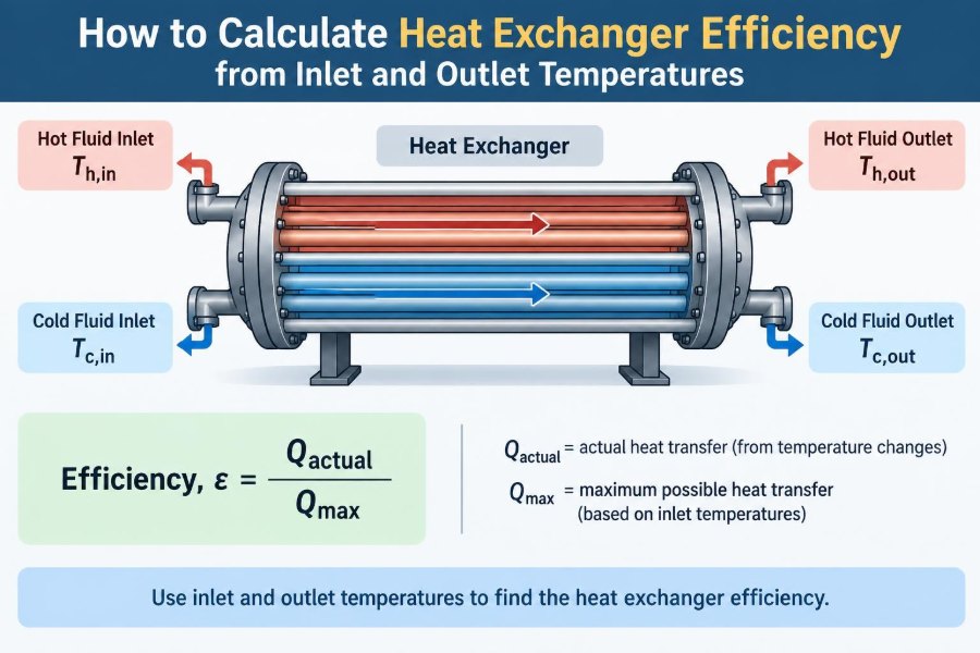

A heat exchanger can look deceptively simple on a process flow diagram: two streams enter, heat passes through a wall, and two streams leave. Yet a few temperature readings around that equipment can reveal whether a utility is being wasted, a process target is being missed, or a fouling problem may be developing.
Imagine a plant engineer checking a cooler after a production change. The hot product leaves warmer than expected, while the cooling-water outlet is only slightly warmer than its inlet. Is the exchanger inefficient? Possibly—but temperatures alone must be interpreted with the flow arrangement, heat-capacity rates, and operating constraints in mind.
Students encounter the same challenge in design courses. An exercise may provide four temperatures and ask for “efficiency,” but that word can refer to several related performance measures. Choosing the wrong definition can produce a neat calculation with little physical meaning.
The most useful temperature-based measure for most heat exchangers is effectiveness: the actual heat transfer compared with the maximum heat transfer theoretically possible under the same inlet conditions. This article shows how to calculate it, check the result, and understand what it can—and cannot—tell you.
🌡️ Start with What a Heat Exchanger Does
A heat exchanger transfers thermal energy from a hotter fluid to a colder fluid across a separating surface. The fluids may be water, steam, oil, air, refrigerant, food product, or a reacting process stream.
In an ideal insulated exchanger, energy lost by the hot stream equals energy gained by the cold stream. No heat needs to be created; it is simply redistributed from a higher-temperature stream to a lower-temperature stream.
Common equipment includes shell-and-tube exchangers, plate exchangers, double-pipe units, finned-tube air coolers, condensers, and evaporators. Their construction differs, but the energy-balance logic begins in the same place.
🧭 Why “Efficiency” Needs a Careful Definition
In everyday language, efficiency means getting a large useful result from a given input. For heat exchangers, however, there is no single universally applicable efficiency based only on temperatures.
A thermal energy balance can indicate how much heat was transferred. Effectiveness, usually written as ε, indicates how close that transfer came to the thermodynamic maximum available from the entering streams.
Other measures may be called efficiency in industry, including a temperature approach, heat-recovery fraction, overall heat-transfer coefficient, or utility savings. Before calculating anything, state the chosen metric explicitly.
🎯 Use Effectiveness for the Standard Temperature Method
Heat-exchanger effectiveness is defined as:
ε = Qactual / QmaxHere, Qactual is the actual rate of heat transfer. Qmax is the maximum possible rate of heat transfer if the exchanger had unlimited area and conductance while retaining the same inlet temperatures and flow conditions.
For an ordinary sensible-heat exchanger with no phase change, effectiveness falls between zero and one. A value near zero means little temperature change; a value nearer one means the exchanger uses much of the available temperature-driving potential.
📥 Gather the Four Temperatures First
Label the streams by temperature rather than by the equipment nozzles. You need the hot-stream inlet and outlet temperatures, Th,in and Th,out, plus the cold-stream inlet and outlet temperatures, Tc,in and Tc,out.
- Hot inlet: the temperature of the stream entering hot.
- Hot outlet: the temperature of that stream leaving cooler.
- Cold inlet: the temperature of the stream entering cold.
- Cold outlet: the temperature of that stream leaving warmer.
Temperatures may be recorded in °C or K because temperature differences have the same numerical size in both scales. Do not use Fahrenheit differences interchangeably with Celsius or kelvin differences.
🔍 Confirm Which Stream Is Hot and Which Is Cold
The hot stream is the one with the higher inlet temperature, and the cold stream has the lower inlet temperature. Normally, the hot-stream temperature drops and the cold-stream temperature rises.
If both streams appear to warm, or both appear to cool, pause before calculating. A measurement may be assigned to the wrong line, the exchanger may have heat loss or gain to its surroundings, or process conditions may be changing rapidly.
Correct stream identification prevents a common error: subtracting temperatures in an order that creates an apparently negative duty for a perfectly normal exchanger.
⚖️ Calculate Each Stream’s Heat-Capacity Rate
Temperature change alone does not tell us how much heat a stream carries. A large flow of water changing by 2°C can transfer more energy than a small flow of oil changing by 20°C.
For each stream, calculate the heat-capacity rate:
C = ṁ Cpṁ is mass flow rate and Cp is specific heat capacity. The common units are kW/K when ṁ is in kg/s and Cp is in kJ/(kg·K).
If specific heat varies substantially over the temperature range, use an appropriate average value or calculate enthalpy differences from reliable property data. The constant-Cp approximation is often adequate for modest temperature ranges in liquids.
🧮 Find the Actual Heat Transfer Rate
For the hot side, the actual heat duty is:
Qh = Ch (Th,in − Th,out)For the cold side, it is:
Qc = Cc (Tc,out − Tc,in)Under steady, well-insulated conditions, Qh and Qc should be approximately equal. Small differences occur from measurement uncertainty, rounding, heat loss, and imperfect estimates of flow or heat capacity.
If the mismatch is large, do not quietly average the values. Investigate the data and operating condition first.
🚦 Identify the Minimum Heat-Capacity Rate
Compare Ch and Cc. The smaller value is Cmin, and the larger is Cmax.
Cmin = smaller of Ch and CcThe stream with Cmin has the smaller ability to absorb or release heat per degree of temperature change. It therefore experiences the larger temperature change for a given heat duty.
This concept is central to effectiveness. The limiting stream, not simply the hottest or coldest stream, determines the theoretical upper bound on sensible heat transfer.
🏁 Calculate the Maximum Possible Heat Transfer
For two single-phase streams, the maximum theoretical duty is:
Qmax = Cmin (Th,in − Tc,in)The inlet temperature difference is the largest driving temperature difference available to the exchanger. In the limiting ideal case, the stream with Cmin could approach the inlet temperature of the other stream.
This equation does not say the outlet temperatures will actually become equal. Real exchangers have finite area, finite heat-transfer coefficients, pressure-drop limits, and nonideal flow distribution.
✅ Calculate Effectiveness from the Energy Balance
Now divide the actual duty by the maximum duty:
ε = Qactual / [Cmin (Th,in − Tc,in)]Use the heat duty from the side with the more reliable measurements, or use a reconciled value after checking the energy balance. Report the result as a decimal or multiply by 100 for a percentage.
A result of ε = 0.72 means the exchanger transfers 72% of the maximum sensible heat that its inlet temperatures and limiting heat-capacity rate allow.
🧾 Use Temperature-Only Forms When the Limiting Side Is Known
If the hot stream has the minimum heat-capacity rate, its temperature drop directly gives effectiveness:
ε = (Th,in − Th,out) / (Th,in − Tc,in)If the cold stream has the minimum heat-capacity rate, use its temperature rise:
ε = (Tc,out − Tc,in) / (Th,in − Tc,in)These forms are convenient because the flow rates and heat capacities cancel. But they are valid only after correctly identifying which stream has Cmin.
🧠 Understand Why the Limiting Stream Controls
Picture two people carrying thermal energy in buckets. One stream has a small bucket per degree of temperature change; the other has a much larger bucket. The smaller bucket fills or empties faster as heat crosses the exchanger wall.
For example, if a low-flow process liquid is cooled by a high flow of water, the liquid may undergo a large temperature drop while the cooling water warms only slightly. The process liquid may be the Cmin stream even though it begins much hotter.
This is why using only the hot-side temperature drop as “efficiency” can be misleading without heat-capacity-rate information.
🧪 Work Through a Complete Hypothetical Example
Suppose a process oil enters a cooler at 150°C and leaves at 90°C. Cooling water enters at 25°C and leaves at 45°C. Assume the calculated heat-capacity rates are Ch = 4 kW/K for oil and Cc = 12 kW/K for water.
The hot-side duty is 4 × (150 − 90) = 240 kW. The cold-side duty is 12 × (45 − 25) = 240 kW, so the measurements satisfy the energy balance exactly in this hypothetical case.
Since Ch is smaller, Cmin = 4 kW/K. The maximum duty is 4 × (150 − 25) = 500 kW. Therefore:
ε = 240 / 500 = 0.48, or 48%The shortcut agrees: (150 − 90)/(150 − 25) = 60/125 = 0.48.
🔁 Recognize Parallel Flow and Counterflow
In parallel flow, both fluids enter from the same end and travel in the same direction. Their temperature difference is largest near the inlet and falls rapidly along the exchanger.
In counterflow, the fluids enter from opposite ends. This arrangement usually maintains a more favorable temperature driving force along the exchanger and can achieve higher effectiveness for comparable conditions.
Temperature readings alone may not reveal the arrangement, but the arrangement matters when comparing measured effectiveness with design predictions or troubleshooting a unit.
↔️ Know When Temperature Crossover Is Normal
In a counterflow exchanger, the cold outlet can be warmer than the hot outlet. This is called temperature crossover, and it does not violate the second law of thermodynamics.
Heat still flows locally from the warmer side of the wall to the cooler side. Counterflow simply allows the exiting cold stream to approach the hot-stream inlet temperature while the exiting hot stream approaches the cold-stream inlet temperature at the opposite end.
A parallel-flow exchanger cannot show this crossover for two sensible streams. If observed data suggest it in parallel flow, check labels and instrumentation.
📊 Compare the Key Temperature-Based Performance Measures
| Measure | Typical expression | What it answers |
|---|---|---|
| Heat duty | Q = CΔT |
How much heat is being transferred? |
| Effectiveness | Q/Qmax |
How much of the theoretical maximum is achieved? |
| Temperature approach | Difference between selected outlet and opposing inlet temperatures | How closely do streams approach one another? |
| LMTD | Logarithmic mean temperature difference | What is the average driving force for design or rating? |
| Overall conductance | UA = Q/(FΔTlm) |
How much heat-transfer capability does the unit provide? |
These measures are related but not interchangeable. Effectiveness is particularly valuable for comparing performance against the maximum imposed by inlet conditions, whereas LMTD and UA are commonly used in sizing and detailed rating calculations.
📐 Separate Effectiveness from LMTD Efficiency
Some plant discussions use “heat-exchanger efficiency” to mean actual duty divided by a design duty, or measured UA divided by clean-design UA. Those can be useful maintenance indicators, but they are not the same as effectiveness.
The log mean temperature difference, or LMTD, captures how the temperature driving force varies from one end of an exchanger to the other. It is used in the relation Q = UAΔTlm, with a correction factor where required.
Do not calculate Q/Qmax and call it a fouling factor. A changing effectiveness can result from fouling, but it can also result from changes in flow rate, inlet temperatures, fluid properties, or bypassing.
🛠️ Follow a Practical Calculation Workflow
- Record stable hot and cold inlet and outlet temperatures.
- Confirm stream identity, flow direction, and whether phase change occurs.
- Obtain mass flow rates and suitable heat-capacity data.
- Calculate
Ch,Cc, and each side’s heat duty. - Check whether the two duties agree within expected measurement uncertainty.
- Set
Cminto the smaller heat-capacity rate. - Calculate
Qmax = Cmin(Th,in − Tc,in). - Calculate and report
ε = Qactual/Qmax, including the operating conditions.
This sequence is more reliable than jumping directly to a temperature ratio because it exposes inconsistent data early.
🧯 Check for Basic Physical Plausibility
For an insulated sensible exchanger, the hot outlet should not be colder than the cold inlet, and the cold outlet should not be hotter than the hot inlet. Such readings would imply local heat transfer from cold to hot without external work or a phase-change complication.
Also check that effectiveness is not negative or greater than one. A value above one almost always signals a unit conversion error, wrong temperature tag, incorrect flow estimate, inappropriate property value, or a system boundary that misses an additional heat source.
These checks are not mere bookkeeping. They distinguish a calculation problem from an operating issue that deserves investigation.
📏 Treat Sensor Quality as Part of the Calculation
A calculated effectiveness is only as trustworthy as the temperature, flow, and property inputs. A sensor installed in a poorly mixed pipe section may not represent the bulk fluid temperature.
Temperature errors matter most when a stream has a small measured temperature change. For instance, a 1°C uncertainty has a far larger relative effect on a 3°C water rise than on a 50°C process-stream drop.
- Use calibrated instruments and verify their operating range.
- Measure where the fluid is well mixed and away from dead legs.
- Compare values from redundant instruments when available.
- Use time-averaged data for processes with normal fluctuations.
💧 Account for Heat Losses and Extra Heat Sources
The equal-duty assumption works best when the exchanger and nearby piping are insulated and the process is at steady state. Real equipment may exchange heat with ambient air, receive heat tracing, or have a pump adding a small amount of energy to a circulating fluid.
If the hot-side and cold-side duties differ, the energy balance can be written more generally as:
Qhot released = Qcold gained + QlossesIn large industrial exchangers, modest external losses may be negligible compared with process duty. In a small laboratory rig or lightly insulated skid, they can be material and should not be ignored automatically.
♨️ Handle Condensers and Evaporators Differently
The simple C = ṁCp method applies most directly when both streams remain single phase. During condensation or boiling, a fluid can transfer substantial energy at nearly constant temperature through latent heat.
For a condenser, calculate duty from the condensing stream’s enthalpy change rather than only a temperature drop. The same principle applies to an evaporator, where the refrigerant absorbs latent heat.
Effectiveness concepts can still be used, but definitions require care because one stream may have an effectively very large heat-capacity rate during phase change. Use appropriate property data and the exchanger’s specific rating method.
🧊 Consider Variable Properties and Viscous Fluids
Water often has a relatively stable specific heat over modest operating ranges. Oils, polymer solutions, gases at wide temperature changes, and process mixtures may not.
As a viscous fluid cools, its viscosity can rise. That may reduce turbulence near the wall, lower the heat-transfer coefficient, and increase pressure drop. A temperature-only effectiveness value can reveal changed performance, but it cannot identify this mechanism by itself.
For rigorous work, use temperature-dependent properties or enthalpy data and consider a segmented exchanger calculation.
🧱 Recognize What Fouling Does to Performance
Fouling is the buildup of scale, biological growth, corrosion products, coke, or deposited solids on heat-transfer surfaces. It adds thermal resistance between the two fluids and often reduces the exchanger’s UA.
At otherwise comparable inlet temperatures and flow rates, fouling commonly reduces duty and effectiveness. It may also increase pressure drop, especially when deposits narrow flow passages.
A falling effectiveness is a useful warning signal, but compare like with like. A cooler can show a lower effectiveness on a day when utility flow is reduced even if its surface is perfectly clean.
📈 Trend Comparable Data Instead of Chasing One Reading
A single performance calculation is a snapshot. A trend built from stable operating periods is more informative for maintenance and operations decisions.
Track effectiveness together with hot and cold inlet temperatures, both flow rates, pressure drops, production rate, and utility conditions. This context helps separate a gradual heat-transfer decline from a normal change in process demand.
When possible, normalize comparisons around similar flow rates and inlet temperatures. An exchanger does not have one fixed effectiveness under every operating condition.
🚧 Avoid the Most Common Calculation Mistakes
- Using the larger heat-capacity rate in
Qmax: this overstates the possible duty and understates effectiveness. - Confusing a temperature drop with heat duty: heat capacity rate must be considered.
- Mixing mass and volumetric flow: convert volumetric flow using density before applying
ṁCp. - Ignoring phase change: temperature may remain nearly constant while duty is large.
- Using design temperatures with actual flows: keep all inputs from the same operating condition.
- Assuming every duty mismatch means fouling: measurement and boundary errors are common alternatives.
🔄 Distinguish Rating, Design, and Monitoring Problems
A design problem asks what exchanger area is needed for a specified duty and terminal temperatures. Engineers often use LMTD or the effectiveness–NTU method for this purpose.
A rating problem asks how an existing exchanger will perform at stated flow rates and inlet conditions. It may require UA, geometry, flow arrangement, and property data.
A monitoring problem asks whether a running exchanger is behaving differently from its normal baseline. Temperature-based effectiveness is especially practical here because the required measurements are often already available.
🧮 Connect Effectiveness to NTU When More Detail Is Needed
The number of transfer units is defined as NTU = UA/Cmin. It combines exchanger conductance with the limiting stream’s heat-capacity rate.
For a specified flow arrangement, effectiveness can be related to NTU and the heat-capacity-rate ratio, Cr = Cmin/Cmax. Counterflow and parallel-flow exchangers have different equations because their temperature profiles differ.
This relationship helps engineers move from observed temperatures to an estimate of performance capability. It should be applied with the correct flow arrangement and correction method; shell-and-tube pass arrangements can be more complex than ideal counterflow.
🏭 Use the Result to Make Better Operating Decisions
If effectiveness is lower than expected, first determine whether the consequence is operationally meaningful. A product may still meet its outlet-temperature target because utilities are abundant, while another exchanger with the same effectiveness may constrain throughput.
Possible responses include increasing utility flow within pressure-drop limits, adjusting process flow, cleaning surfaces, correcting bypassing, improving insulation, or reviewing control-valve operation. Each option has trade-offs involving energy use, production impact, equipment limits, and maintenance risk.
Never increase flow blindly. More flow can improve heat transfer, but it can also raise pumping cost, vibration risk, erosion potential, and pressure drop.
🧰 Document Assumptions with Every Result
A useful calculation record includes temperature tags, timestamps, flow rates, property sources, units, estimated uncertainty, exchanger configuration, and whether phase change was present.
Also state whether the reported duty came from the hot side, cold side, or reconciled average. This makes the result auditable and allows someone else to repeat it after a turnaround, instrumentation change, or process modification.
Good documentation turns a one-time classroom answer or spreadsheet cell into a reliable performance baseline.
📌 Know the Core Principle
Calculating heat-exchanger effectiveness from inlet and outlet temperatures is fundamentally an energy-balance exercise. Determine how much heat actually moves, determine how much could move under the inlet conditions, and compare the two.
The key equations for sensible, steady-state service are:
C = ṁCp
Qactual = C(temperature change)
Qmax = Cmin(Th,in − Tc,in)
ε = Qactual/Qmax
The calculation becomes meaningful only when temperature measurements are credible, stream heat-capacity rates are correctly evaluated, and limits such as heat loss, variable properties, phase change, and changing operating conditions are acknowledged.
A temperature reading becomes a useful heat-exchanger performance measure when it is tied to an energy balance, the limiting heat-capacity rate, and the real operating context. Used this way, effectiveness is a practical bridge between first-principles thermodynamics and day-to-day engineering decisions. 🧪🌡️📈