
A cement kiln, steel furnace, refinery heater, or power boiler can look very different from the outside. Yet each may send a large volume of hot exhaust gas up a stack every minute. That gas is mostly nitrogen, water vapor, and other combustion products—but it can also contain carbon dioxide, the greenhouse gas many industries are trying to manage.
Carbon capture is often pictured as a machine that simply “filters out” CO₂. The real process is more interesting. Engineers must separate one molecule from a fast-moving, dirty, low-pressure gas mixture, then prepare that CO₂ for transport, use, or permanent storage.
The challenge is not whether CO₂ can be separated. It can. The challenge is doing it reliably with acceptable energy use, equipment size, solvent consumption, emissions control, and cost.
Understanding the separation step explains why carbon capture systems include tall columns, heat exchangers, compressors, pumps, and extensive gas-cleaning equipment—not just a single filter.
🏭 What Industrial Exhaust Actually Contains
Industrial exhaust, often called flue gas when it comes from combustion, is a mixture rather than a pure stream. Its composition depends on the fuel, process, air supply, and pollution-control equipment upstream.
For a typical air-fired combustion source, nitrogen is usually the largest component because air contains much more nitrogen than oxygen. CO₂, water vapor, residual oxygen, and trace contaminants share the remaining space. A cement plant also releases CO₂ directly from limestone decomposition, not only from fuel burning.
This matters because separation equipment must find CO₂ among molecules that are chemically similar in size or present in much larger quantities.
🎯 The Separation Problem in One Sentence
Carbon capture works by creating a stronger preference for CO₂ than for the other gases in an exhaust stream. That preference may come from a chemical reaction, physical solubility, molecular sieving, selective transport through a membrane, or a very cold phase-change process.
Think of sorting mixed recyclables. A process is useful only if it identifies the desired material, handles the flow rate, and releases a sufficiently clean product. Carbon capture follows the same logic at molecular scale.
🌡️ Why Temperature, Pressure, and Composition Matter
A separation method that performs well for a concentrated, pressurized gas may be inefficient for a dilute gas near atmospheric pressure. These conditions determine the “driving force” available to move CO₂ into a solvent, across a membrane, or onto a solid surface.
Hot gas can also damage or weaken some capture materials. Most systems therefore condition flue gas before the main absorber, adjusting temperature and removing particles or reactive contaminants.
Engineers begin with measurements: gas flow rate, CO₂ concentration, temperature, pressure, humidity, and impurity levels. Without credible feed data, equipment sizing is largely guesswork.
🧪 Post-Combustion Capture: Removing CO₂ After Burning
Post-combustion capture treats exhaust after fuel has been burned with air. It is often discussed for existing boilers, furnaces, and kilns because the core combustion process can remain broadly familiar.
Its central difficulty is dilution. CO₂ is mixed with a large nitrogen-rich gas stream at relatively low pressure, so the equipment must contact a substantial volume of gas.
Amine-based absorption is the most established route in this category, although solid sorbents, membranes, and other approaches are also being developed or applied in suitable cases.
🧴 Amine Solvents: CO₂’s Chemical Partner
Many post-combustion designs use a water-based liquid containing an amine, an organic compound that can reversibly react with CO₂. The word “reversibly” is crucial: the solvent must capture CO₂ in one part of the plant and release it in another.
The reaction increases how much CO₂ the liquid can hold compared with plain water. Nitrogen and oxygen are much less readily captured, allowing the treated flue gas to leave with less CO₂.
Different amine formulations trade reaction speed, loading capacity, stability, corrosion behavior, and regeneration energy. There is no universally best solvent for every exhaust source.
🗼 Inside the Absorber Column
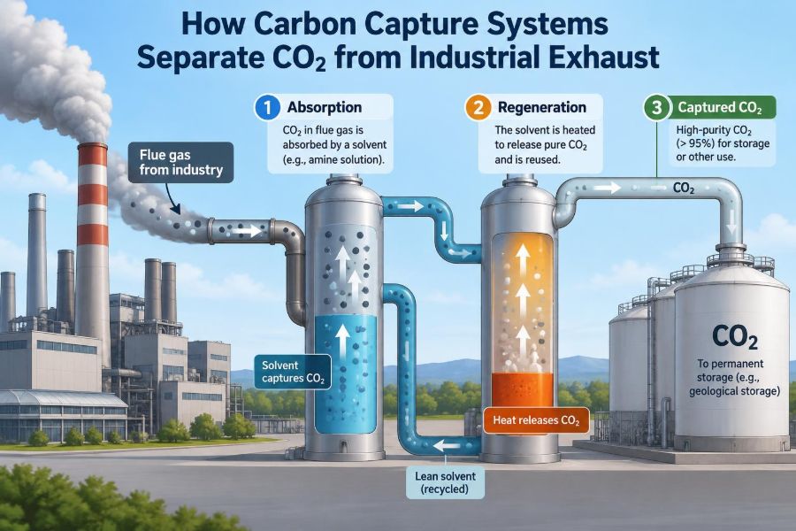
The absorber is commonly a tall vertical column filled with structured or random packing. Flue gas enters near the bottom and rises, while cooled lean solvent flows downward from the top.
This countercurrent arrangement keeps fresh solvent meeting gas that has already lost much of its CO₂, while CO₂-rich incoming gas contacts solvent that has already absorbed some CO₂. The pattern makes efficient use of the available chemical driving force.
The packing creates a large wet surface area without requiring an impossibly large open tank. CO₂ moves from gas into the liquid film and reacts with the solvent.
💨 What Leaves the Top of an Absorber
Gas leaving the absorber is often called treated gas. It contains far less CO₂ than the incoming flue gas, but it may still carry water vapor or tiny solvent droplets.
A water-wash section and mist eliminator near the top of the column help reduce solvent loss. This is more than housekeeping: solvent emissions affect operating cost, environmental management, and worker exposure controls.
The remaining gas may then pass through a stack or through downstream equipment, depending on the plant configuration and applicable permit requirements.
🔄 Rich and Lean Solvent: The Continuous Loop
Solvent leaving the absorber has taken up CO₂ and is called rich solvent. It is pumped to a regeneration section. Solvent that has released most of its CO₂ is called lean solvent and returns to the absorber.
A rich-lean heat exchanger usually transfers heat from the hot regenerated solvent to the cooler rich solvent. This recovers energy internally and reduces the external heat required later.
Maintaining the correct solvent circulation rate is a balancing act. Too little liquid leaves capture capacity unused; too much increases pumping demand and can create hydraulic problems in the column.
🔥 The Stripper Releases a Concentrated CO₂ Stream
The regeneration column is often called a stripper or desorber. Heat reverses the solvent-CO₂ reaction, releasing CO₂ from the rich solvent and restoring the liquid for reuse.
Steam supplied at the base, commonly through a reboiler, heats the solvent. As vapor rises through the column, it strips CO₂ from the descending liquid.
The overhead stream contains CO₂ plus substantial water vapor. Cooling and condensing much of that water sends it back to the process, leaving a more concentrated CO₂ stream for purification and compression.
⚡ Why Regeneration Uses So Much Energy
The largest energy demand in many solvent systems is not pumping exhaust gas through the absorber. It is supplying heat to regenerate the solvent. Energy is needed to break the solvent-CO₂ association, heat circulating liquid, and produce stripping steam.
When capture is added to a power plant, this demand can reduce net electrical output unless additional fuel or energy is supplied. In an industrial plant, it can compete with steam needed elsewhere.
This is often called the energy penalty. It does not mean capture is impossible; it means heat integration is a central design problem rather than an afterthought.
♨️ Heat Integration Can Change the Economics
A well-integrated plant looks for usable heat already present in process streams. For example, low- or medium-temperature steam, waste heat, or carefully arranged heat exchangers may reduce the new energy infrastructure required.
However, “waste heat” is not automatically free. It may be intermittent, at the wrong temperature, already committed to another duty, or too remote to recover economically.
Pinch analysis and detailed heat-and-material balances help engineers identify realistic opportunities instead of assuming every warm stream can power a capture unit.
🧹 Gas Cleanup Protects the Capture System
Particles, sulfur oxides, nitrogen oxides, and other contaminants can foul equipment or degrade solvents. Their importance depends on the capture technology and concentration, but pretreatment is commonly essential.
Typical upstream controls may include particulate removal, sulfur control, cooling, and polishing steps. Oxygen can also contribute to solvent degradation in some formulations, particularly when heat and impurities are present.
A capture plant designed around clean laboratory gas may struggle on a real industrial site if contaminant variability is ignored.
🧪 Solvent Degradation and Reclamation
Heat, oxygen, acid gases, and metal ions can gradually alter an amine solvent. Degraded compounds may reduce capture performance, increase corrosion risk, or contribute to foaming.
Plants manage this through filtration, monitoring, careful chemical control, and reclamation—a process that removes certain heat-stable salts and degradation products from a solvent slipstream.
Solvent management produces secondary material streams that need appropriate handling. Carbon capture shifts emissions management; it does not remove the need for responsible chemical operations.
🫧 Foaming: A Small Problem With Big Consequences
Foam can form when contaminants, degradation products, oils, or suspended solids alter liquid behavior. In an absorber or stripper, foam disrupts gas-liquid contact and can carry solvent into places it should not go.
Operators may notice unstable pressure drop, poor capture performance, or increased solvent losses. Antifoam chemicals can help, but they are not a substitute for finding the contamination source.
Good sampling practice matters. A sample drawn from one quiet line may fail to reveal solids or hydrocarbons entering elsewhere in the loop.
🧱 Solid Sorbents Capture CO₂ on a Surface
Instead of dissolving CO₂ in a liquid, solid sorbents hold it on or within porous materials. Examples include activated materials, zeolites, functionalized solids, and other engineered adsorbents.
These systems often operate in cyclic beds. One bed captures CO₂ while another is regenerated, then valves switch their duties. The solid is not usually consumed, but its performance can decline if it is poisoned, degraded, or physically damaged.
Solid processes can avoid circulating large liquid volumes, but they introduce different challenges: heat management, bed pressure drop, particle attrition, moisture sensitivity, and complex valve sequencing.
⏱️ Pressure Swing and Temperature Swing Adsorption
Adsorption processes regenerate solids by changing conditions. In pressure swing adsorption, lowering pressure helps release previously adsorbed gas. In temperature swing adsorption, heating drives the CO₂ off the solid.
Vacuum can also be used to create a lower CO₂ partial pressure. Each option has trade-offs between electricity use, heat use, cycle time, equipment complexity, and product purity.
These methods are especially relevant when a gas stream is already pressurized or when a material has strong selectivity under the available conditions.
🧬 Membranes Let Some Molecules Move Faster
A membrane is a thin barrier that allows certain gases to pass through more readily than others. CO₂ can permeate faster than nitrogen through many membrane materials, creating a CO₂-enriched stream on one side and a CO₂-depleted stream on the other.
The separation is driven by a pressure difference or partial-pressure difference. Because a single stage may not achieve both high recovery and high purity, membrane systems may use multiple stages, recycle streams, compression, or vacuum pumps.
Membranes are compact and modular, but their performance can be reduced by contaminants, condensation, plasticization, or insufficient driving force.
❄️ Cryogenic Separation Uses Cold Instead of Chemistry
Cryogenic processes cool gas enough to condense or separate CO₂-rich phases. They can be attractive for streams that already have high CO₂ concentrations or favorable pressure conditions.
For dilute, near-atmospheric flue gas, cooling enormous volumes to very low temperatures is generally demanding. Water and impurities must also be controlled because they can freeze or cause operational problems.
Cryogenic methods are therefore not a default solution for every stack, but they can fit certain concentrated process streams and purification duties.
🔥 Oxy-Fuel Combustion Changes the Exhaust Composition
Another strategy is to change combustion itself. Oxy-fuel combustion burns fuel in oxygen rather than ordinary air, often with recycled flue gas used to moderate flame temperature.
Because most nitrogen from air is absent, the exhaust can be mainly CO₂ and water vapor. Condensing the water can leave a CO₂-rich stream that may require less conventional separation.
The catch is oxygen production. Producing, handling, and integrating large oxygen flows requires major equipment and energy, so the system-wide comparison must include the air separation unit.
🔧 Pre-Combustion Capture Starts With Syngas
In pre-combustion capture, fuel is converted into a synthesis gas, often containing carbon monoxide and hydrogen. A water-gas shift reaction can convert carbon monoxide and water into CO₂ and additional hydrogen.
The resulting CO₂ can be separated at elevated pressure, which can favor physical solvents or other techniques. The hydrogen-rich fuel may then be used for power or industrial heating.
This route is structurally different from retrofitting a conventional air-fired boiler. It is most relevant where gasification or hydrogen-production pathways already make process sense.
📊 Comparing Major Capture Routes
| Route | Main separation basis | Typical fit | Key design concern |
|---|---|---|---|
| Post-combustion absorption | Reversible chemical reaction | Existing flue-gas sources | Regeneration heat and solvent control |
| Solid adsorption | Selective surface uptake | Streams suited to cyclic operation | Bed cycling, heat transfer, impurities |
| Membranes | Selective permeation | Pressurized or modular applications | Pressure driving force and staging |
| Oxy-fuel combustion | CO₂-rich exhaust formation | New or heavily modified combustion systems | Oxygen supply and integration |
| Pre-combustion capture | CO₂ removal from shifted syngas | Hydrogen and gasification pathways | Whole-process configuration |
The table is a map, not a technology ranking. Feed conditions, available heat, product specification, site space, and the fate of captured CO₂ determine which route is credible.
🗜️ Compression Makes CO₂ Transportable
CO₂ leaving a capture unit is not necessarily ready for a pipeline or storage site. Compression raises its pressure, usually in stages with cooling between stages to limit compressor discharge temperatures.
Water removal is especially important because water can cause corrosion or form hydrates under certain conditions. Depending on the intended destination, additional purification may be needed to control oxygen, nitrogen, sulfur compounds, or other trace constituents.
The product specification is set by the transport and storage or utilization system, not by the capture column alone.
🧭 Capture Is Only One Part of Carbon Management
A complete carbon capture and storage chain includes separation, dehydration, compression, transport, injection, and long-term monitoring where geological storage is used. A failure or bottleneck in any link can limit the value of the others.
Captured CO₂ may also be used in industrial processes. But use is not automatically permanent climate management: the climate outcome depends on whether and when the CO₂ is released again.
Engineers should distinguish capture rate at the plant from the broader performance of the entire chain, including energy supply and downstream handling.
🏗️ Why Cement and Steel Need Different Designs
Cement production is notable because calcining limestone releases process CO₂ even if the kiln’s fuel changes. Capture can therefore address emissions that are not eliminated simply by switching from fossil fuel to a low-carbon energy source.
Steel plants can have multiple CO₂-bearing streams with different pressures and contaminants, such as blast furnace gas, basic oxygen furnace gas, or reformer-related streams in alternative production routes. Selecting one capture point may be simpler than treating every vent.
Source-specific engineering matters more than slogans such as “install carbon capture on industry.”
📐 Designing Around Flow Variability
Real facilities do not always operate at steady full load. Startup, shutdown, product changes, fuel shifts, and maintenance can change gas flow and composition quickly.
Capture equipment must tolerate these conditions without flooding columns, overheating solvent, sending off-spec CO₂ downstream, or wasting excessive energy at low load. Control systems use measurements such as pressure drop, temperature profiles, liquid levels, and CO₂ analyzers to maintain stable operation.
A design based only on average flow may look efficient on paper and prove fragile in daily service.
🛡️ Safety and Operability Are Core Design Duties
Carbon capture plants handle hot liquids, steam, rotating compressors, pressurized CO₂, and chemicals that may be corrosive or irritating. Safe operation requires conventional process-safety discipline: hazard identification, relief design, containment, ventilation, isolation, procedures, and training.
CO₂ itself is not flammable, but high concentrations can displace oxygen and create an asphyxiation hazard, especially in enclosed or low-lying spaces. Pressurized releases can also produce cold jets and poor visibility.
Materials selection deserves close attention because aqueous amines, impurities, and temperature gradients can create corrosion conditions that are not obvious from a simple equipment list.
📏 Measuring Performance Without Misleading Yourself
Capture performance can be described in several ways: fraction of inlet CO₂ removed, CO₂ product purity, solvent circulation rate, energy consumed per amount captured, and emissions avoided across the facility. These measures answer different questions.
For example, a high removal percentage does not by itself show whether the plant’s additional energy came from a low-carbon source. Likewise, a pure CO₂ product is not useful if recovery is too low for the project’s objective.
Clear boundaries and transparent mass balances prevent apples-to-oranges comparisons.
🚧 Common Mistakes in Early Carbon Capture Planning
- Treating exhaust as clean and constant: contaminant spikes and operating changes can dominate maintenance needs.
- Ignoring steam and power supply: regeneration and compression must be integrated into the host facility.
- Sizing only the absorber: stripping, cooling water, solvent storage, reclamation, and CO₂ compression also need space.
- Leaving transport decisions until late: CO₂ specifications and delivery pressure affect upstream design.
- Assuming removal equals permanent storage: downstream destination and monitoring remain essential.
Early feasibility work should therefore connect process simulation, utility studies, site layout, emissions controls, and CO₂ logistics.
🧠 The Core Principle: Create, Then Reverse, Selectivity
Every capture technology relies on selectivity: CO₂ must be favored over other gases. In an amine plant, the solvent selectively reacts with CO₂ in the absorber, then heat reverses that interaction in the stripper.
In a membrane, CO₂ moves preferentially through a material. In adsorption, it binds more strongly to a surface. In cryogenic systems, phase behavior provides the distinction. The engineering task is to exploit that preference repeatedly, efficiently, and safely.
The best system is not the one with the most impressive single component. It is the one whose separation mechanism, energy supply, impurity controls, and CO₂ destination work together as a dependable whole.
Carbon capture separates CO₂ by giving it a different chemical or physical path than the rest of an exhaust stream—and successful projects design the entire path, not just the first separation step. ♻️🏭🧪