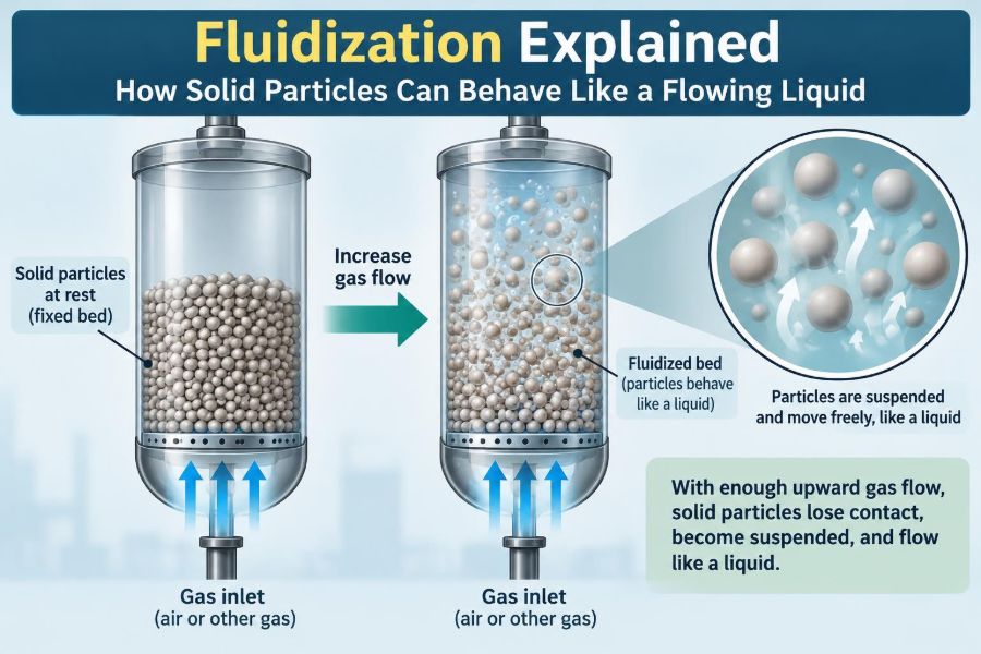

Picture dry sand in an hourglass. It pours, forms a level surface, and slips around obstacles, yet every grain is undeniably solid. Now imagine pushing gas upward through a bed of those grains until the bed swells, bubbles, and can be moved through pipes almost like a liquid.
That change is fluidization. It is one of chemical engineering’s most useful examples of a simple physical idea producing remarkably versatile industrial equipment.
Fluidized beds help process powders in catalytic cracking units, boilers, dryers, coaters, and pharmaceutical manufacturing. They can deliver excellent heat transfer and mixing, but their apparently liquid-like behavior can also conceal difficult design and operating problems.
Understanding what holds particles up, what makes a bed stable, and what causes it to become turbulent turns a memorable classroom demonstration into practical engineering knowledge.
🧱 What Fluidization Means
Fluidization occurs when an upward-flowing fluid, usually a gas or liquid, exerts enough drag on a bed of particles to counteract their effective weight. The particles become suspended and can move relative to one another.
The word does not mean that solids melt or dissolve. Each particle remains solid; the whole collection simply acquires some bulk behaviors associated with a fluid, such as flow, mixing, and a nearly level upper surface.
🔍 The Packed Bed Starting Point
Before fluidization, particles rest in a packed bed. Their weight is supported partly by contacts with neighboring particles and partly by the vessel base. Fluid travels through the void spaces between them.
At low flow rates, particles barely move. Increasing flow causes a larger pressure drop because the fluid must squeeze through the same narrow passages more quickly.
⬆️ Drag Is the Lifting Force
A moving fluid pulls on particle surfaces through drag. In a bed, the relevant effect is the total drag imposed on all particles, not merely the force on one isolated grain.
As superficial velocity rises, drag rises. Superficial velocity is the fluid volumetric flow rate divided by the empty cross-sectional area of the vessel; it is a convenient design velocity, even though actual flow through voids is faster.
⚖️ The Minimum Fluidization Condition
The pivotal point is minimum fluidization. At this condition, the pressure force across the bed is just enough to balance the bed’s effective weight per unit area.
The corresponding superficial velocity is called minimum fluidization velocity, commonly written as Umf in technical work. Above it, additional gas flow no longer mainly increases pressure drop; instead, it expands or changes the structure of the bed.
📉 Why Pressure Drop Reaches a Plateau
For a uniform bed with negligible wall effects, the pressure drop at minimum fluidization is approximately related to the solids weight supported by the fluid. A useful conceptual balance is:
pressure drop × bed area ≈ buoyancy-corrected weight of particles
Once the bed is fluidized, its average pressure drop often remains roughly constant over a range of gas velocities. This is a diagnostic signature, not an absolute rule: distributor behavior, fines, agglomerates, and changing bed inventory can complicate a real measurement.
🫧 Why a Fluidized Bed Looks Like a Liquid
A well-fluidized bed can support an object, transmit pressure, and seek a level surface. If the vessel is tilted slightly, particles may redistribute much as a liquid would.
The analogy has limits. Particle collisions, friction, bubbles, and clusters create behaviors that ordinary liquids do not show. Treating a fluidized bed as a perfect liquid is a useful first approximation and a poor final design method.
🌬️ Gas Fluidization and Liquid Fluidization
Both gases and liquids can fluidize solids, but their behavior differs because liquids are denser and more viscous. Liquid-fluidized beds often expand more smoothly and show fewer large voids.
Gas-fluidized beds more readily form bubbles, slugs, and particle clusters. This makes gas-solid systems especially common in reactors and combustors, while liquid-solid systems are often used where controlled contact or classification is needed.
🧪 Particle Size Changes Everything
Small particles have more surface area relative to mass and are strongly affected by cohesive forces. Large particles have greater inertia and often need higher velocities to suspend.
Particle size also determines settling behavior, entrainment risk, and how rapidly gas passes through the bed. A broad size distribution can make the bed behave differently from a bed of nearly uniform particles.
🧲 Cohesion Can Prevent Smooth Fluidization
Fine powders may cling together through van der Waals attraction, moisture bridges, electrostatic charge, or sticky surface deposits. These interparticle forces can be comparable to, or larger than, the forces trying to separate particles.
The result may be channels, lumps, or a bed that moves as plugs rather than as freely circulating particles. Drying, conditioning, vibration, altered particle formulation, or mechanical agitation may help, but each remedy must suit the process material.
📊 Geldart Groups Offer a Practical Map
Engineers often use the Geldart classification to anticipate gas-fluidization behavior from particle size and density difference. It is a helpful empirical framework, not a substitute for pilot testing.
| Group | Typical behavior | Common concern |
|---|---|---|
| A | Easily aerated; bed expands before obvious bubbling | Entrainment of fines |
| B | Bubbles form readily near minimum fluidization | Bubble-driven bypassing |
| C | Very fine, cohesive powders | Poor or difficult fluidization |
| D | Large or dense particles | Spouting and high velocity needs |
Real powders can sit between groups, change behavior with humidity, or evolve during reaction. Classification guides questions; it does not deliver a guaranteed operating window.
🎈 Bubbling Fluidized Beds
In many gas-solid beds, gas above Umf collects into bubbles that rise through a dense emulsion phase of particles and gas. The appearance can resemble boiling, although the mechanism is gas flow rather than evaporation.
Bubbles promote circulation and mixing, but gas inside a bubble can bypass solids contact. Reactor performance therefore depends not only on average residence time but also on how gas exchanges between bubbles and the dense phase.
🌊 Slugging Is a Larger-Scale Instability
When bubbles grow until they span most of a narrow vessel, they become slugs. A slug can lift a large section of solids and produce cyclic pressure fluctuations.
Slugging can be desirable in a specifically designed device, but it is often troublesome because it reduces contact uniformity and stresses equipment. Vessel diameter, bed height, gas velocity, and particle properties all influence the tendency.
🌪️ Turbulent and Fast Fluidization
At higher velocities, bubble boundaries become less distinct, solids circulation intensifies, and the bed enters turbulent fluidization. At still higher velocity, substantial solids are carried upward and must be separated and returned.
This fast fluidization regime is central to circulating fluidized-bed systems. It enables high solids throughput and excellent gas-solid contact, but requires careful control of solids inventory and return flow.
🔄 Circulating Fluidized Beds
A circulating fluidized bed, or CFB, intentionally transports particles out of the riser with gas. Cyclones or other separators remove solids from the gas, and a return leg sends them back to the lower part of the system.
Continuous circulation can transfer heat, catalyst, or reactive solids between vessels. The system is powerful because solids do not simply sit in one vessel; they become a controllable moving inventory.
🏭 The Distributor Sets the Foundation
The gas distributor at the vessel bottom is not a minor fitting. It must spread incoming gas sufficiently evenly so that one region does not receive most of the flow.
A good distributor creates enough pressure drop to reduce sensitivity to local bed variations, without imposing excessive energy use or becoming prone to plugging. Perforated plates, nozzles, and porous designs are chosen according to solids, gas cleanliness, temperature, and maintenance needs.
🕳️ Channeling Defeats Contact
Channeling occurs when gas finds preferred paths through a bed while other zones remain poorly fluidized. It can arise from a poor distributor, nonuniform particle packing, cohesive material, leaks, or internal obstructions.
Channeling is harmful when uniform reaction, drying, or heating is required. A sight glass may reveal localized eruptions, but pressure signals, temperature differences, and product variability can be equally important clues in closed industrial equipment.
🌡️ Heat Transfer Is a Major Advantage
Particles repeatedly contact each other and immersed surfaces in a fluidized bed. This motion often yields high heat-transfer rates compared with a fixed bed of the same solids.
That is why fluidized beds are attractive for strongly exothermic reactions, combustion, and drying. Good mixing can reduce hot spots, although it cannot eliminate them automatically when feed distribution or reaction rates are uneven.
⚗️ Mass Transfer and Reaction Contact
Fluidization renews gas films around particles and mixes solids, improving opportunities for heat and mass transfer. In a catalytic reactor, this can expose reactant gas to active catalyst more uniformly than a poorly contacted fixed bed.
However, rapid bulk mixing does not guarantee that every particle sees identical conditions. Bubble bypassing, catalyst deactivation, diffusion inside porous particles, and short-circuiting can still limit conversion or selectivity.
🔥 Combustion Applications
Fluidized-bed combustion suspends fuel particles, inert bed material, or sorbents in upward air. The intense mixing and thermal capacity of the solids can support relatively even temperatures.
Engineers must still manage fuel size, ash behavior, emissions control, and erosion. Materials that soften or melt can create sticky deposits and cause particles to agglomerate, jeopardizing bed movement.
🛢️ Catalytic Cracking as a Landmark Example
Fluid catalytic cracking uses fine solid catalyst circulating between a reactor and a regenerator. Hydrocarbon feed contacts hot catalyst in the reactor, while deposited carbonaceous material is removed by burning in the regenerator.
The example illustrates why circulation matters: the solid is both catalyst and heat carrier. It also illustrates complexity, because catalyst attrition, separation efficiency, and temperature balance are integral to operation.
💊 Drying, Granulation, and Coating
In fluidized-bed dryers, warm gas suspends wet particles while removing moisture. The large exposed surface area and motion can make drying efficient for suitable particulate materials.
Related equipment can spray binder or coating liquid onto fluidized particles. The process must balance wetting and evaporation: too little liquid may produce poor coating, while too much can cause agglomeration and defluidization.
🧭 Residence Time Is Not One Simple Number
Particles and gas do not always spend the same amount of time in a fluidized vessel. Some particles can circulate quickly, while others linger; gas may travel through emulsion regions or through bubbles.
For design and troubleshooting, engineers consider residence-time distribution rather than relying only on volume divided by flow rate. Tracer tests and validated models can reveal bypassing or dead zones that an average calculation hides.
📏 Estimating Minimum Fluidization
Correlations based on particle Reynolds number, density, size, fluid viscosity, and bed voidage are commonly used to estimate Umf. The calculations provide a starting point for sizing blowers and setting initial operating conditions.
They are sensitive to assumptions about particle shape and representative diameter. Irregular, porous, coated, or broad-distribution particles often depart from ideal correlation behavior, so measured pressure-drop curves remain valuable.
🧰 Essential Measurements in Operation
Reliable operation depends on observing both the gas system and the solids system. A single flow indicator rarely tells the full story.
- Pressure taps at several elevations can reveal bed density changes, distributor issues, and unstable regimes.
- Temperature measurements detect reaction imbalance, poor mixing, or loss of cooling.
- Gas flow, composition, and solids inventory help interpret pressure trends.
- Particle-size analysis tracks attrition, loss of fines, and incoming material variability.
🪨 Attrition and Entrainment Consume Solids
Particles collide with one another, vessel walls, cyclones, and internal tubes. These impacts can break fragile solids into fines, a process called attrition.
Fine particles are easier for gas to carry out of the bed, causing entrainment. Separation equipment recovers valuable solids and protects downstream machinery, but no separator is perfect; make-up solids and fines handling may be part of normal operation.
🧱 Erosion Threatens Hardware
High-velocity solids can erode bends, nozzles, cyclone inlets, and heat-exchanger tubes. Erosion rate depends on velocity, impact angle, particle hardness, concentration, and materials of construction.
Good layouts avoid unnecessarily sharp turns, while wear liners and sacrificial components can extend service life. Inspection plans should target known high-wear zones rather than waiting for a leak or performance loss.
🚨 Defluidization Is a Process Upset
Defluidization occurs when a bed loses its freely moving state. Causes include reduced gas flow, wet or sticky solids, agglomeration, foreign objects, distributor plugging, or a sudden shift in particle-size distribution.
The consequences can include temperature excursions, blocked flow paths, and difficult restart procedures. In reactive or high-temperature services, operating procedures need clear limits and safe response actions tailored to the plant.
🧯 Startup and Shutdown Need Deliberate Control
Starting with a cold, settled bed requires gradual establishment of flow and, where relevant, controlled heating. Uneven heating can promote condensation, sticking, or thermal stress.
During shutdown, solids may settle and compact. Preventing unwanted backflow, managing residual heat, and ensuring that combustible or reactive materials are handled safely are process-specific requirements, not generic checkboxes.
🧑🏭 A Practical Troubleshooting Sequence
When a bed performs poorly, avoid changing many variables at once. First establish whether the problem is flow delivery, solids condition, distribution, heat balance, or downstream separation.
- Compare actual gas flow and pressure profiles with normal operating behavior.
- Check for changes in feed moisture, particle size, density, or contamination.
- Review temperature patterns and recent operating changes.
- Inspect distributors, filters, cyclones, and accessible internals during a safe outage.
- Test corrective changes in a controlled sequence and document the response.
🧠 Common Mental Models That Mislead
One mistake is assuming that “more gas” always improves fluidization. Excess velocity can increase entrainment, erosion, power demand, and undesirable bypassing.
Another is assuming a uniform-looking bed is automatically well contacted. A bed may appear active while gas preferentially travels through bubbles or channels. Pressure, composition, temperature, and product data are needed alongside visual observation.
🧩 Scale-Up Is More Than Making the Vessel Wider
Small laboratory beds can behave very differently from industrial units. Larger diameter changes bubble growth, wall influence, distributor design, heat removal, and the meaning of a representative measurement.
Scale-up typically combines dimensional analysis, established correlations, pilot work, and conservative mechanical design. Because solids behavior is material-specific, uncertainty should be explicitly allowed for rather than hidden behind a single calculated value.
🧑🔬 Laboratory Demonstrations Build Intuition
A transparent column containing dry particles and air can demonstrate bed expansion, bubbling, and the pressure-drop transition. It is an excellent way to connect force balance with what students can see.
Even a demonstration needs safeguards. Dust generation, static charge, compressed-gas hazards, and airborne particles require appropriate containment, ventilation, eye protection, and procedures. Never improvise with combustible dusts.
🌱 Energy and Environmental Trade-Offs
Fluidized systems can intensify heat and mass transfer, potentially reducing equipment size or improving thermal integration. But moving gas and solids requires energy, and erosion or attrition can increase material consumption.
The best choice depends on the complete process: feed properties, product requirements, emissions controls, maintenance access, and available utilities. Fluidization is an enabling tool, not a universal efficiency upgrade.
🎯 The Core Principle to Remember
Fluidization begins when upward fluid drag balances the effective weight of a particle bed. From that point onward, the interaction between gas flow, particle properties, vessel geometry, and internals determines whether the bed expands smoothly, bubbles, circulates, or becomes unstable.
Its value lies in controllable contact: solids can mix, transfer heat, react, dry, and circulate in ways a static packed bed cannot easily achieve. Its challenge is that this contact is dynamic, so sound design must respect the real behavior of the particles rather than only the idealized liquid analogy.
A fluidized bed is not a liquid, but understanding why it behaves like one gives engineers a powerful way to process solids at scale. 🧪🌬️⚙️