
A reactor can look calm from the outside while behaving very differently within. A jacket may show a normal average temperature, instruments may indicate that cooling water is flowing, and the product may appear on specification—until a sampling result, a pressure rise, or an inspection reveals that one region has been running much hotter than the rest.
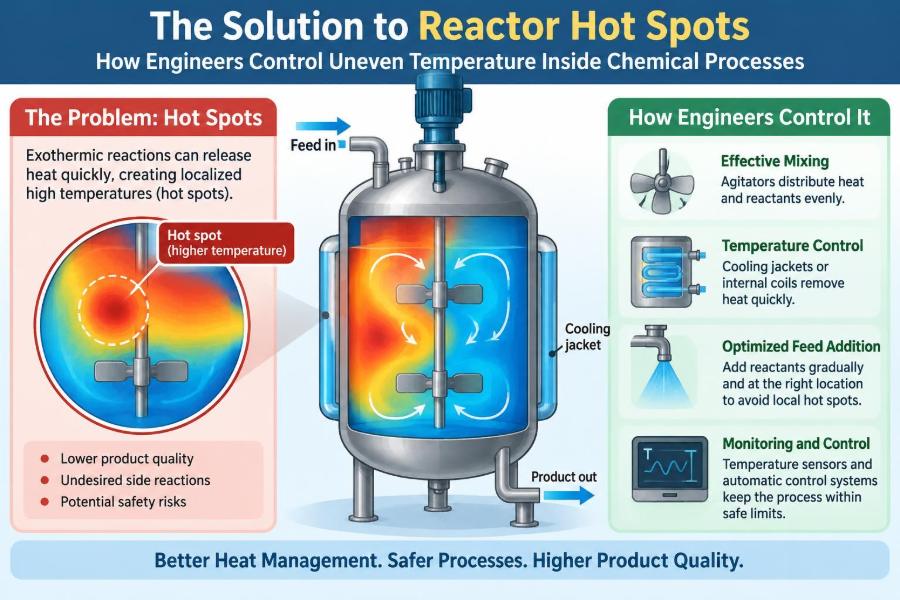
That local region is called a hot spot: an area where temperature is substantially higher than the reactor average. It is a familiar challenge in processes involving exothermic reactions, meaning reactions that release heat.
The consequences range from lower yield and catalyst damage to unwanted by-products, accelerated corrosion, and, in severe cases, loss of temperature control. The engineering challenge is not simply to remove heat. It is to remove it from the right place, at the right rate, while ensuring reactants are distributed evenly.
Understanding hot spots connects transport phenomena, reaction engineering, equipment design, instrumentation, and operating discipline. The same ideas apply whether the equipment is a stirred tank, a packed-bed reactor, a polymerization vessel, or a large industrial reactor with several feed points.
🔥 What a Reactor Hot Spot Actually Is
A hot spot is a localized temperature maximum inside a reactor or reactor system. It may occur near a feed nozzle, in the center of a catalyst bed, beside a heat-transfer surface, or in a poorly mixed zone.
It is not necessarily visible from outside the vessel. A single temperature measurement reports conditions at its own location, not everywhere in the process. The reactor-average temperature can therefore look acceptable while a small volume experiences conditions that are chemically and mechanically unsafe.
⚗️ Why Exothermic Reactions Create the Problem
Every reaction has an enthalpy change. For an exothermic reaction, heat is released as reactants form products. If this heat is removed as quickly as it is generated, temperature remains controlled.
Problems begin when local heat generation exceeds local heat removal. Temperature rises, and the reaction may accelerate. This makes more heat, which raises temperature further: a feedback loop that is central to thermal runaway risk.
📈 The Temperature–Rate Feedback Loop
Many reaction rates increase strongly with temperature, commonly described by the Arrhenius relationship. The details depend on the reaction, but the practical lesson is simple: a modest local temperature rise can produce a disproportionately faster reaction.
That faster reaction consumes reactants and generates heat in the same location. In a well-designed process, mixing and cooling interrupt this loop. In a poorly distributed system, the loop can intensify before bulk instruments detect it.
🧭 Average Temperature Can Hide Local Danger
Engineers often speak of reactor temperature, but a real reactor has a temperature field: temperature varies with position and time. In an ideal, perfectly mixed vessel, that variation would be small. Industrial equipment only approaches that ideal.
Consider a hypothetical 10 m³ stirred reactor whose average temperature is on target. If a small zone near the reactant inlet is much warmer, it can still create degradation products or trigger a fast side reaction. The average reading does not cancel out the local chemistry.
🌀 Mixing Is the First Line of Defense
Mixing transports reactants, heat, and suspended solids through the vessel. Good mixing reduces concentration gradients, so a fresh reactant charge does not remain concentrated near the point where it enters.
It also moves hot liquid toward cooled surfaces and brings cooler liquid back toward the reaction zone. Mixing does not create cooling capacity, but it lets installed cooling capacity reach the material that needs it.
🔄 Mixing Time Is Not the Whole Story
Mixing time is often measured as the time needed for a tracer to become acceptably uniform throughout a vessel. It is useful, but it may not predict the short-lived conditions immediately after a reactive feed enters.
A reactor can have a satisfactory overall mixing time and still develop a microenvironment of high concentration and high temperature at the feed point. For fast reactions, engineers must compare the time scales of mixing, reaction, and heat transfer rather than relying on one mixing metric.
📍 Feed Location Changes the Chemistry
Where a reactant enters matters. Adding a reactive stream beside a cold jacket, into an impeller discharge zone, or through several distributed nozzles can produce very different local conditions.
A feed point placed in a stagnant region may allow reactant accumulation. A point too close to a heat-transfer surface may create deposition or locally extreme viscosity. The preferred position depends on vessel geometry, fluid properties, reaction speed, and the impeller’s flow pattern.
💧 Feed Rate and Dosing Strategy Matter
Even a well-located feed can create a hot spot if it enters too quickly. A rapid dose delivers a high local concentration of reactant, and therefore a high local reaction rate, before the vessel can disperse it.
Controlled semi-batch operation often addresses this by metering one reactant gradually. The feed rate is then a safety and quality variable, not merely a production scheduling choice. In some processes, multiple smaller feed points reduce the peak local concentration.
🧊 Heat Transfer Has a Local Limit
Heat leaves a reactor through jackets, internal coils, external exchangers, or recirculation loops. The overall heat-transfer rate depends on area, temperature driving force, flow conditions, and resistance through vessel walls or fouling layers.
Cooling surfaces cannot instantly extract heat from the vessel center. Heat must first travel through the fluid, usually by convection driven by mixing. A large jacket area may therefore be insufficient if circulation within the reactor is weak.
🧱 Fouling Quietly Reduces Cooling Performance
Fouling is the buildup of deposits on heat-transfer surfaces. It adds thermal resistance, reducing the ability of a jacket, coil, or exchanger to remove heat at a given temperature difference.
Fouling can be especially troublesome in polymerizing, crystallizing, or solids-handling systems. It may develop gradually, so an operating recipe that was once comfortable becomes increasingly close to its cooling limit. Trend data and cleaning plans are part of hot-spot prevention.
🛢️ Viscosity Makes Temperature Gradients More Likely
High-viscosity fluids resist flow and often mix less readily. As viscosity rises, an agitator may circulate material poorly, and heat transfer near the vessel wall can deteriorate.
This is common in polymerization, concentrated formulations, and reactions that create solids. An impeller suitable at the start of a batch may be inadequate near the end. Engineers may use different impeller designs, variable speed, or process staging to handle the changing fluid behavior.
🧪 Fast Reactions Need More Than Bulk Control
For slow reactions, a reactant may disperse before much conversion occurs. For very fast reactions, substantial conversion can occur within milliseconds or seconds of contact. Local composition then determines local heat release.
These systems may require specialized injection devices, high-shear mixing, static mixers upstream of the reactor, or diluted feeds. The goal is to control the contact event itself, rather than expecting the full vessel to correct it afterward.
🏭 Stirred-Tank Reactors and Their Vulnerable Zones
In a continuous stirred-tank reactor, or CSTR, agitation is intended to make the contents nearly uniform. In practice, dead zones can form behind baffles, below certain impellers, near the liquid surface, or in poorly swept vessel regions.
Multiple impellers may be needed in tall vessels. Baffles suppress swirling and help convert impeller energy into useful circulation. Neither feature is universal; their design must suit gas dispersion, solids suspension, shear sensitivity, and cleaning requirements.
🧺 Packed-Bed Reactors Develop Axial Hot Spots
In a packed-bed catalytic reactor, reactants flow through stationary catalyst particles. As an exothermic reaction proceeds, heat is released along the flow direction, often producing an axial temperature peak known as a hot spot.
The peak commonly occurs where reaction rate is greatest, not necessarily at the outlet. As reactants are consumed, heat generation may decrease downstream. Catalyst activity, feed composition, inlet temperature, and flow distribution all influence where the peak appears.
🌬️ Flow Maldistribution in Catalyst Beds
Fluid does not always divide evenly across a catalyst bed. Channels, wall flow, poor inlet distribution, damaged internals, or settling can send more reactant through one region than another.
That region then experiences higher reaction rates and temperatures. Temperature sensors at only one radial position may miss the issue. Distributor design and bed loading procedures are therefore as important as the catalyst chemistry.
🧯 Quench Streams and Interstage Cooling
A common packed-bed solution is to split a duty across multiple beds with cooling between them. Interstage exchangers remove heat before the next catalyst layer receives the stream.
A quench stream injects a cooler fluid between beds to lower temperature directly. Quenching can be effective and responsive, but it changes flow, composition, and sometimes equilibrium. It must be designed as part of the reaction system, not treated as a universal emergency fix.
🧬 Polymerization Requires Special Care
Many polymerization reactions release significant heat and can become more difficult to mix as molecular weight and viscosity increase. Local overheating may change molecular-weight distribution, promote gel formation, or create deposits that further impair cooling.
Engineers may control initiator addition, monomer feed, solvent fraction, and agitation power. Because the material properties change during the batch, laboratory calorimetry and pilot-scale data are particularly valuable for defining conservative operating limits.
🌡️ Instrumentation Must See the Right Places
A temperature sensor is only as informative as its location. A thermowell near a jacket may read cooler than the reactor core; one beside a feed nozzle may measure a local spike that does not represent the bulk.
Multiple sensors at different elevations or bed positions create a more useful picture. In packed beds, thermocouple multipoints can reveal movement of the reaction zone. Sensor readings should be interpreted with awareness of response time, calibration, and installation geometry.
📊 Use Trends, Not Just Alarm Limits
A high-temperature alarm is necessary, but the rate of temperature change can provide earlier warning. A rising temperature despite increased coolant flow may indicate growing heat generation, fouling, a feed error, or loss of mixing.
Useful monitoring compares related variables: reactor temperature, jacket inlet and outlet temperatures, coolant flow, agitator power, feed rate, pressure, and composition where available. No single signal diagnoses every problem, but their combined pattern often narrows the cause.
🎛️ Control Loops Need a Thoughtful Design
Basic temperature control adjusts cooling or heating utility flow to hold a temperature setpoint. For exothermic reactors, feed-rate control can be equally important because it directly influences heat generation.
Cascade control is often used when a reactor-temperature controller sets the target for a faster utility-side loop. This can reduce the effect of utility pressure or flow disturbances. The best architecture depends on process dynamics, available measurements, valve behavior, and the consequences of a delayed response.
🧠 Model-Based Tools Improve Operating Decisions
Heat and material balances are the starting point for predicting hot spots. More detailed models may include reaction kinetics, heat-transfer coefficients, mixing behavior, and spatial flow patterns.
Computational fluid dynamics can help visualize circulation and identify likely poorly mixed regions, particularly during design or troubleshooting. It is not a substitute for representative operating data: model predictions depend heavily on assumptions about turbulence, rheology, reaction rate, and boundary conditions.
🧫 Calorimetry Defines the Thermal Envelope
Reaction calorimetry measures heat release under controlled conditions. It helps engineers estimate how much heat a process generates, how quickly it may be released, and how changing feed conditions affect the duty.
Adiabatic calorimetry examines what can happen when heat removal is absent or severely limited. Together, such testing supports safer scale-up, but test conditions must represent the real chemistry, including impurities, phase behavior, accumulation, and realistic concentrations.
🚨 Separate Normal Control from Emergency Protection
Normal control keeps the process near its operating target. Independent protective layers address deviations that control may not manage, such as loss of agitation, utility failure, an incorrect charge, or an unexpectedly fast reaction.
Depending on the process, safeguards can include high-high temperature trips, automatic feed isolation, emergency cooling, inhibitor or quench addition, pressure relief, and defined shutdown procedures. Their selection requires a formal hazard review; safeguards should not be assumed effective without verifying their response and capacity.
🧰 Mechanical Design Supports Thermal Control
Agitator size, impeller type, baffle arrangement, vessel aspect ratio, coil layout, nozzle positions, and recirculation connections all shape the temperature field. These choices are difficult and costly to change after installation.
Design should consider credible off-normal conditions, not just nominal production. A system that performs well with fresh catalyst, clean coils, and low viscosity may behave differently after campaigns, at turndown, or during start-up.
🔍 Commissioning Finds Issues Before Full Throughput
Water trials and nonreactive circulation tests can reveal flow imbalance, weak agitation, valve limitations, and unexpected heat-transfer behavior. They do not reproduce every chemical effect, but they provide valuable evidence about equipment performance.
During reactive commissioning, stepwise increases in feed and duty allow teams to compare observed response with the design basis. Clear limits, trained operators, and a preplanned response to deviations are essential during this learning period.
⚠️ Common Mistakes That Create Hot Spots
- Using one bulk temperature as proof of uniform conditions: it can miss localized reaction zones.
- Scaling agitation by rpm alone: vessel size, impeller diameter, fluid density, and viscosity change what a speed setting means.
- Increasing feed to recover production: this can exceed local mixing or cooling capability before average temperature rises.
- Ignoring fouling and utility variability: both reduce available heat removal.
- Treating a hot spot solely as a cooling problem: concentration gradients and flow maldistribution may be the underlying cause.
🛠️ A Practical Troubleshooting Sequence
When abnormal temperature behavior appears, first stabilize the process according to site procedures: reduce or stop reactive feeds if appropriate, maximize verified cooling within operating limits, and confirm agitation and utilities are functioning.
Then investigate systematically. Compare current conditions with prior stable runs, inspect trends, verify instruments, check utility-side temperatures and flow, review additions and feed composition, and assess whether viscosity, fouling, or catalyst condition has changed. Avoid making several uncontrolled adjustments at once; that obscures cause and effect.
📝 Questions to Ask During Process Design
- Where is heat generated fastest, and how quickly can it be transported away?
- Can reactants accumulate if a feed begins before adequate mixing is established?
- Which operating changes increase viscosity, reduce cooling, or shift the reaction zone?
- What measurements would reveal a local temperature rise early enough to act?
- What happens during loss of coolant, agitation, power, or feed control?
These questions turn hot-spot control from a late-stage troubleshooting exercise into a design requirement.
🤝 Operations, Maintenance, and Engineering Share the Task
Hot-spot prevention is not solved by equipment design alone. Operators recognize unusual trends, maintenance preserves agitator and utility performance, and process engineers keep recipes, limits, and models aligned with real plant behavior.
Management of change is especially relevant. A new raw-material supplier, altered feed concentration, different cleaning interval, or control-system modification can change heat generation or removal in ways that are not obvious from the batch record alone.
✅ The Core Principle: Balance Heat Generation and Removal Locally
The central idea is straightforward: safe reactor operation requires local heat removal and reactant dispersion to keep pace with local heat generation. A satisfactory average temperature is valuable, but it is not enough by itself.
Strong designs combine appropriate chemistry data, effective mixing, well-placed feeds, reliable heat-transfer surfaces, representative measurements, responsive control, and independent safeguards. Each layer addresses a different reason that one part of a reactor might become hotter than the rest.
Engineers control reactor hot spots by designing and operating for what happens at the point of reaction, not merely what an average instrument reports. That local perspective protects product quality, equipment integrity, and process safety. 🧪🌡️⚙️