
A batch is nearly ready to transfer, but the operator asks a deceptively simple question: “Has the tank mixed long enough?” A level reading and an agitator speed are available, yet neither one directly answers it.
This question appears in water treatment, food production, polymer make-down, blending, neutralization, and pharmaceutical manufacturing. Starting the agitator is not the same as achieving a uniform tank.
Mixing time affects product consistency, reaction performance, sampling confidence, and batch cycle time. Run too briefly and a sample may not represent the vessel; run far longer than necessary and energy, schedule, and equipment life are wasted.
A sound estimate does not require pretending that every tank behaves perfectly. It starts with basic process parameters, uses correlations carefully, and confirms the result when the consequence of poor mixing is significant.
🌀 What Mixing Time Actually Means
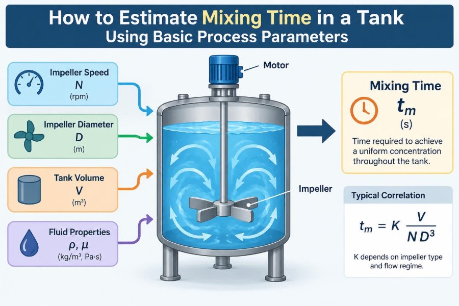
Mixing time is the time required after a disturbance for a specified property to become acceptably uniform throughout a vessel. The property might be tracer concentration, pH, temperature, dissolved salt, or suspended-solids concentration.
It is not simply the time for liquid to make one trip around the tank. A recirculating flow can return quickly while poorly exchanged zones near the wall, surface, bottom, or behind internals remain different.
🎯 Uniformity Needs a Numerical Definition
No real process reaches mathematically perfect uniformity. Engineers therefore define an acceptance band around the final steady value, often expressed as a percentage deviation.
For a tracer test, a practical definition may be the time until the measured signal stays within a chosen band of its final value. Tighter bands produce longer reported mixing times, even in the same tank under unchanged conditions.
Always record the criterion with the result: “mixing time to the selected concentration tolerance” is more useful than a bare number of minutes.
🧭 Start by Identifying the Mixing Duty
The right estimate depends on what must be mixed. Blending two low-viscosity liquids is a different duty from dissolving powder, maintaining solids suspension, dispersing gas, or removing heat from a jacketed vessel.
- Liquid blending: distribution of one liquid or soluble additive through another.
- Solids suspension: preventing particles from resting on the vessel bottom.
- Gas dispersion: breaking and distributing bubbles, often with a sparger.
- Heat transfer: reducing temperature gradients near coils or jackets.
- Reaction mixing: controlling local composition where reactants meet.
A bulk blending time can look acceptable while local conditions at an addition point remain unsuitable for a fast reaction.
📐 The Basic Tank Geometry
Begin with a scaled sketch and dimensions. The working liquid height, tank diameter, impeller diameter, impeller clearance from the bottom, and number of impellers all influence circulation.
For a vertical cylindrical tank, the working liquid volume is approximately:
V = πT²H / 4where T is tank diameter and H is liquid height. Use the actual working volume, not nominal vessel capacity; headspace is not part of the liquid being mixed.
🧱 Tank Shape Changes the Flow Path
A flat-bottom tank, dished-bottom tank, cone-bottom vessel, and horizontal drum encourage different circulation patterns. A tall vessel may need multiple impellers because one impeller’s pumped flow does not effectively cover the full liquid height.
A useful first geometric indicator is the aspect ratio H/T. It does not predict mixing time by itself, but it signals whether a single central impeller is likely to have a difficult vertical mixing task.
⚙️ Know the Impeller, Not Just the Motor
The motor rating tells how much power may be available; it does not reveal the flow pattern in the tank. Mixing is governed more directly by impeller type, diameter, speed, and position.
Axial-flow impellers, such as pitched-blade turbines and hydrofoils, pump strongly along the shaft direction and are often effective for bulk liquid turnover. Radial-flow turbines discharge outward toward the tank wall and are commonly selected where shear or gas dispersion is needed.
Two impellers with the same diameter and rotational speed can therefore have very different mixing behavior.
🔄 Calculate the Tip Speed
Impeller tip speed is a quick operating descriptor:
u_tip = πDNHere, D is impeller diameter and N is rotational speed in revolutions per second. Tip speed is relevant to shear-sensitive materials, vortex risk, and mechanical limits, but it is not a standalone predictor of blend time.
A small impeller at very high speed can have a similar tip speed to a larger, slower impeller while producing a different bulk circulation pattern.
🌊 Use Pumping Capacity for a First Estimate
For many turbulent liquid-blending duties, the impeller pumping capacity is the most intuitive starting point. It is estimated by:
Q = NqND³Q is volumetric flow rate and Nq is the dimensionless pumping number. The value of Nq depends on impeller design and installation, so use supplier data or a credible reference for the specific impeller where possible.
This equation shows why diameter matters so much: pumped flow changes with D³. Increasing impeller diameter can improve bulk turnover more efficiently than simply raising speed, subject to torque, clearance, and process constraints.
⏱️ Convert Pumped Flow into Turnover Time
A nominal turnover time is:
t_turnover = V / QThis is the time corresponding to one vessel volume at the estimated impeller discharge flow. It is a useful scale, not the finished answer.
Actual blending commonly requires several nominal turnovers because the discharge stream does not sweep every point equally and because flow must exchange material among circulation loops. Treat turnover time as a reality check: an estimated blend time much shorter than a small fraction of one turnover deserves scrutiny.
📊 A Practical Correlation Form
Mixing-time correlations are often expressed in dimensionless form:
Nt = C(T/D)^a(H/T)^b(Re)^cwhere t is mixing time, C, a, b, and c are correlation constants, and Re is the mixing Reynolds number. Some correlations include baffle, impeller-clearance, or multi-impeller terms.
The important limitation is that the constants are not universal. A correlation developed for a baffled, turbulent water system should not be used unquestioned for a viscous, unbaffled, or gas-filled production tank.
🧮 Calculate the Mixing Reynolds Number
The mixing Reynolds number compares inertial and viscous effects:
Re = ρND² / μρ is liquid density and μ is dynamic viscosity. Use consistent units, such as kg/m³, m, s, and Pa·s.
At high Reynolds number, inertial turbulent motion dominates and many water-like blending correlations become more applicable. At lower values, viscosity strongly changes the flow field and mixing-time predictions become less transferable.
🧪 Viscosity Is Often the Hidden Variable
Viscosity may change with temperature, concentration, shear rate, or reaction progress. A syrup-like blend can be easy to mix at the beginning and much harder after cooling or thickening.
For non-Newtonian fluids, one quoted viscosity can be misleading. Shear-thinning materials become less viscous near the impeller but may retain high-viscosity, slow-moving regions elsewhere. In those cases, pilot testing, computational analysis, or vendor design support is often more defensible than a simple turbulent correlation.
🧷 Why Baffles Matter
Baffles are vertical strips mounted on the tank wall. In standard stirred-tank practice, they disrupt bulk swirling and convert more of the impeller’s action into useful top-to-bottom and radial circulation.
Without baffles, a low-viscosity liquid may rotate as a body and form a surface vortex. The impeller can appear energetic while the relative motion needed for efficient mixing is reduced.
Baffle dimensions, number, wall gap, and obstructions all matter. Do not assume a vessel is “baffled” merely because it has probes, a dip pipe, or a few internal supports.
🕳️ Vortexing Is Not Evidence of Good Mixing
A deep surface vortex can pull air into the liquid. That may create foam, oxidation, inaccurate density measurements, pump problems, or an unwanted change in reaction conditions.
Vortexing also redirects energy into rotational motion rather than effective bulk exchange. A quiet surface in a properly baffled tank can indicate better mixing than a dramatic whirlpool.
📍 The Addition Point Alters the Observed Time
A tracer added directly into the impeller discharge may spread much faster than one poured near a stagnant surface corner. This does not necessarily mean either test is wrong; it means the test represents a different addition scenario.
Place a process chemical where the main circulation can capture it promptly, while considering safety, local reaction rate, corrosion, and splash. For fast acid-base neutralization, for example, addition location may be as influential as the final bulk mixing time.
📡 Sampling Location Can Mislead You
A sample valve near the impeller discharge can report a uniform-looking result before the upper or distant region is mixed. Conversely, a poorly flushed sample line can make a well-mixed tank appear slow.
When validating a tank, use multiple measurement locations if practical: near the top, middle, and lower region, while avoiding direct impeller discharge. The slowest representative location is usually more meaningful for setting an operating hold time.
🧫 The Tracer Test Method
A tracer test measures how a detectable, compatible material spreads after a defined addition. Conductivity is convenient for adding a small salt solution to water-like systems; pH, temperature, dye absorbance, or other plant-approved signals may also be suitable.
- Bring the tank to normal working level and operating conditions.
- Run the agitator at the intended speed and establish stable operation.
- Add a small, known tracer pulse at a defined location.
- Record the response over time at one or more locations.
- Determine when the signal remains within the chosen acceptance band.
The tracer amount should be large enough to measure clearly but small enough not to alter density, viscosity, chemistry, or process safety.
📈 Read the Mixing Curve, Not Just One Number
Plotting normalized tracer response against time reveals useful behavior. A rapid rise followed by a slow tail often indicates a main circulation loop plus a poorly exchanged region.
Repeated oscillations can occur when the sensor sits in a recirculating path and alternately sees tracer-rich and tracer-poor fluid. That is why a single threshold crossing is insufficient; the signal should remain within the acceptance band.
🔢 A Hypothetical Water-Like Blend
Consider a hypothetical baffled tank holding 2.0 m³ of water-like liquid. It has a 0.50 m axial-flow impeller turning at 2.0 s⁻¹. If a suitable impeller reference gives Nq = 0.6, the estimated pumped flow is:
Q = 0.6 × 2.0 × 0.50³ = 0.15 m³/sThe nominal turnover time is then 2.0 / 0.15, or about 13 seconds. That does not establish a 13-second mixing time. It says the predicted circulation capacity is substantial relative to vessel volume; a geometry-matched correlation or tracer test is still needed to determine how many turnovers are required for the selected uniformity criterion.
🏗️ Multiple Impellers for Tall Tanks
When liquid height is large relative to tank diameter, one impeller may create distinct upper and lower circulation zones with limited exchange. Adding a second impeller on the shaft can shorten the vertical mixing path and reduce dead zones.
Do not estimate a multi-impeller system by simply doubling the flow from one impeller. Impellers interact through the shared flow field, spacing matters, and the lower impeller may operate in a different local environment from the upper one.
🧯 Coils, Dip Pipes, and Other Internals
Heat-transfer coils, draft tubes, filter elements, level instruments, and feed pipes can either help redirect flow or create sheltered regions. Their effect is highly geometry-specific.
An estimate based on an empty vessel is therefore optimistic when the actual tank contains dense internals. During troubleshooting, compare the installed arrangement—not only the original general-arrangement drawing—with the assumptions behind the calculation.
🪨 Solids Change the Question
For slurries, “uniform concentration” may not be the primary requirement. A process may instead require complete off-bottom suspension, no sediment at the outlet, or acceptable concentration variation during transfer.
Particle size, density difference, loading, and settling rate matter. Raising agitator speed can suspend solids, but it can also increase attrition, power draw, and wear. A liquid-phase blend-time estimate alone is not an adequate solids-suspension design method.
💨 Gas Dispersion Reduces Pumping Capacity
When gas is sparged beneath an impeller, bubbles can alter the flow pattern and reduce effective pumping. This is often described as gas-induced loss of impeller performance.
A tank that mixes well without gas may behave differently during aeration or stripping. Validate the actual operating state, including gas rate and liquid level, rather than relying only on a water test performed with the sparger off.
🌡️ Heat Transfer Has Its Own Timescale
Temperature mixing involves both hydrodynamic blending and heat entering or leaving through a jacket, coil, or external loop. A temperature probe can respond slowly because of its own thermal lag, which should not be confused with tank mixing time.
For temperature-sensitive operations, compare readings from more than one location and account for sensor response. A well-blended tank can still heat slowly if the heat-transfer area or driving temperature difference is limited.
⚡ Power per Unit Volume Is a Screening Tool
Specific power, often written as P/V, is useful for comparing agitation intensity between similar duties. It can help flag an obviously underpowered installation.
However, equal P/V does not guarantee equal mixing time. Impeller pumping efficiency, tank geometry, baffles, viscosity, and internals determine how that power becomes useful circulation. Use power as one input, not a universal answer.
📝 Build a Defensible Estimate Workflow
A practical calculation should be traceable enough that another engineer can review the assumptions. A compact workflow is:
- Define the mixing objective and allowable non-uniformity.
- Collect actual operating volume, liquid properties, geometry, internals, and agitator data.
- Calculate
Re, tip speed, estimatedQ, and nominal turnover time. - Select a correlation only if its geometry and flow regime resemble the application.
- State the predicted time as an estimate with its criterion and operating conditions.
- Confirm with a tracer or process-representative test when risk or uncertainty justifies it.
🚫 Common Estimation Mistakes
- Using nominal tank capacity instead of actual liquid volume.
- Calling one turnover time the mixing time without validation.
- Using motor nameplate power as though all of it reaches the liquid.
- Ignoring baffles, coils, probes, and feed pipes.
- Applying a water correlation to a viscous or non-Newtonian material.
- Measuring only beside the impeller or at one convenient sample port.
- Failing to state the uniformity criterion and tracer addition point.
Most errors come from misplaced confidence in a simple number, not from arithmetic.
🔍 When a Simple Estimate Is Good Enough
A first-pass estimate can be appropriate for low-risk water-like blending in a conventional baffled tank, particularly when the same vessel and impeller arrangement have already been used successfully for similar batches.
It is less suitable as the sole basis for scale-up, safety-critical reaction control, sterile manufacturing, difficult rheology, gas-liquid mixing, or a batch where local concentration can damage product quality. In those cases, testing and more detailed design work provide value because the uncertainty is consequential.
🛠️ Ways to Improve a Slow-Mixing Tank
Before increasing speed, diagnose why the tank is slow. More speed raises power demand and shear, but may not correct a poor flow pattern.
- Install or repair appropriately sized baffles where compatible with cleaning and process needs.
- Use a larger or more suitable impeller to increase bulk pumping.
- Adjust impeller elevation or add an upper impeller for tall liquid levels.
- Move feed points into an effective circulation path.
- Remove, reposition, or account for obstructive internals.
- Reduce viscosity through permitted temperature or formulation changes.
The best modification depends on the duty: a solution blending problem and a solids-settling problem rarely have the same fix.
📋 Document Conditions So Results Travel
A mixing time belongs to a set of conditions, not just a vessel tag. Record liquid level, temperature, viscosity basis, agitator speed, impeller configuration, baffle condition, tracer method, addition point, sensor locations, and acceptance criterion.
This documentation makes later changes visible. If a batch becomes slower after a formulation change, a comparison is possible only when the original basis was preserved.
✅ The Core Principle for Reliable Mixing-Time Estimates
Basic parameters can create a valuable engineering estimate: volume defines the amount to be mixed; impeller size and speed indicate circulation potential; viscosity and Reynolds number describe the flow regime; geometry and baffles determine how completely circulation reaches the vessel.
The estimate becomes credible when it is tied to a clear uniformity target and checked against the real equipment. Treat correlations as structured engineering tools, not substitutes for understanding the flow inside a particular tank.
The most useful mixing-time number is not the shortest calculated time—it is the time demonstrated or conservatively estimated to meet the required uniformity under actual operating conditions. That perspective protects both product quality and process efficiency. 🧪🔄📐