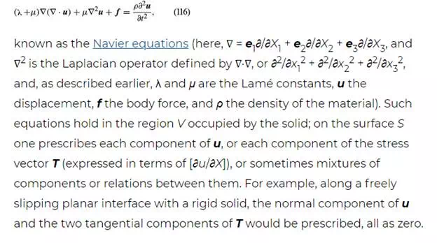
The final equations of the purely mechanical theory of linear elasticity (i.e., when coupling with the temperature field is neglected, or when either isothermal or isentropic response is assumed) are obtained as follows. The stress-strain relations are used, and the strains are written in terms of displacement gradients. The final expressions for stress are inserted into the equations of motion, replacing ∂/∂x with ∂/∂X in those equations. In the case of an isotropic and homogenous solid, these reduce to
Body wave solutions
By looking for body wave solutions in the form u(X, t) = pf (n · X − ct), where unit vector n is the propagation direction, p is the polarization, or direction of particle motion, and c is the wave speed, one may show for the isotropic material that solutions exist for arbitrary functions f if either
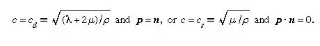
The first case, with particle displacements in the propagation direction, describes longitudinal, or dilatational, waves; and the latter case, which corresponds to two linearly independent displacement directions, both transverse to the propagation direction, describes transverse, or shear, waves.
Linear elastic beam
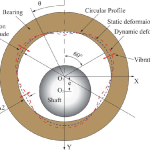
The case of a beam treated as a linear elastic line may also be considered. Let the line along the 1-axis (see Figure 7), have properties that are uniform along its length and have sufficient symmetry that bending it by applying a torque about the 3-direction causes the line to deform into an arc lying in the 1,2-plane. Make an imaginary cut through the line, and let the forces and torque acting at that section on the part lying in the direction of decreasing X1 be denoted as a shear force V in the positive 2-direction, an axial force P in the positive 1-direction, and torque M, commonly called a bending moment, about the positive 3-direction. The linear and angular momentum principles then require that the actions at that section on the part of the line lying along the direction of increasing X1 be of equal magnitude but opposite sign.
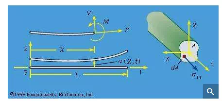
Now let the line be loaded by transverse force F per unit length, directed in the 2-direction, and make assumptions on the smallness of deformation consistent with those of linear elasticity. Let ρA be the mass per unit length (so that A can be interpreted as the cross-sectional area of a homogeneous beam of density ρ) and let u be the transverse displacement in the 2-direction. Then, writing X for X1, the linear and angular momentum principles require that ∂V/∂X + F = ρA ∂2u/∂t2 and ∂M/∂X + V = 0, where rotary inertia has been neglected in the second equation, as is appropriate for disturbances which are of a wavelength that is long compared to cross-sectional dimensions. The curvature κ of the elastic line can be approximated by κ = ∂2u/∂X2 for the small deformation situation considered, and the equivalent of the stress-strain relation is to assume that κ is a function of M at each point along the line. The function can be derived by the analysis of stress and strain in pure bending and is M = EIκ, with the moment of inertia I = ∫A(X2)2dA for uniform elastic properties over all the cross section and with the 1-axis passing through the section centroid. Hence, the equation relating transverse load and displacement of a linear elastic beam is −∂2(EI∂2u/∂X2)/∂X2 + F = ρA∂2u/∂t2, and this is to be solved subject to two boundary conditions at each end of the elastic line. Examples are u = ∂u/∂X = 0 at a completely restrained (“built in”) end, u = M = 0 at an end that is restrained against displacement but not rotation, and V = M = 0 at a completely unrestrained (free) end. The beam will be reconsidered later in an analysis of response with initial stress present.
Comments are closed