
A heat exchanger is easy to overlook until it stops doing its job. The shower turns cold, a car begins to overheat in traffic, or a refrigeration unit struggles to hold temperature. In each case, a device is trying to move thermal energy from one fluid stream to another.
That process can sound abstract when introduced through overall heat-transfer coefficients and logarithmic mean temperature differences. A small bench-top demonstration makes it tangible: warm water enters, cooler water enters somewhere else, temperatures change, and the energy balance either closes—or reveals where the experiment needs work.
This project builds a low-temperature water-to-water heat exchanger from accessible materials and uses it to compare flow arrangements and flow rates. It is suitable for a supervised classroom, laboratory introduction, or careful home demonstration.
The goal is not to reproduce industrial performance. It is to learn how area, temperature driving force, flow direction, and fluid velocity interact, while practicing the measurement habits that make engineering comparisons credible.
🔄 What a heat exchanger actually does
A heat exchanger transfers energy across a solid wall separating two fluids. In this demonstration, hot water flows through a metal tube while cold water flows around the outside of that tube. The streams exchange heat but should not mix.
Heat moves from the higher-temperature stream to the lower-temperature stream. The metal wall conducts heat, while convection carries heat between each moving fluid and the wall.
🏭 Why this small experiment connects to industry
Industrial exchangers appear in chemical plants, power stations, food processing lines, HVAC equipment, and pharmaceutical systems. Shell-and-tube, plate, spiral, and finned designs all apply the same energy-transfer ideas at different scales.
Your model has simpler geometry and far more heat loss relative to its size. Even so, it exposes real design trade-offs: increasing flow can improve convection but requires more pumping effort; adding surface area can increase duty but also create pressure drop and cleaning challenges.
🎯 Define a useful experimental question
Start with one question that can be answered from measured data. For example: How does increasing the cold-water flow rate affect the heat transferred when the hot-water inlet temperature and hot-water flow rate are held approximately constant?
A second, especially instructive question is: Does counter-current flow transfer more heat than co-current flow under comparable inlet conditions? Change one main variable at a time. Otherwise, a temperature difference could result from a changed flow rate, a changed inlet temperature, or both.
🧠 The energy balance behind the measurements
For a liquid stream with no phase change, the heat-transfer rate can be estimated as:
Q̇ = ṁ Cp (Tin − Tout)Here, Q̇ is heat-transfer rate, ṁ is mass flow rate, Cp is specific heat capacity, and temperatures are measured for the same stream. For water near room-to-warm conditions, using approximately 4.18 kJ/(kg·K) is usually adequate for a teaching calculation.
The hot-side calculation uses a temperature decrease. The cold-side calculation uses a temperature increase. Both should produce positive estimates of the heat transferred.
🧰 Choose a simple and safe exchanger design
A practical design is a tube-in-shell exchanger: a coiled copper tube sits inside a larger clear plastic or rigid tube. Hot water passes through the copper coil; cold water enters one end of the outer shell and leaves the other.
Copper conducts heat well and is easy to coil gently. A transparent outer shell lets students see the construction, though transparency is not necessary for performance. Food-grade silicone tubing can work as an inner tube for a qualitative trial, but its low thermal conductivity makes heat transfer much weaker and less predictable.
📦 Gather materials deliberately
Use materials rated for the water temperatures and connections involved. The following set supports a modest, low-temperature experiment:
- Soft copper tubing, roughly 3–5 m long and 6–10 mm outside diameter
- A larger rigid tube or clear housing that can contain the coil and water
- Two water containers: one warm reservoir and one cool reservoir
- Two small pumps, or elevated reservoirs for gravity-driven flow
- Flexible tubing, clamps, fittings, and hose barbs suited to the tubing
- Four thermometers or temperature probes
- A measuring jug or graduated container and a timer
- Insulation such as foam wrap or a towel for the exchanger body
- Trays and towels to contain spills
Do not substitute unknown containers or adhesives where warm water may soften or weaken them. Test every fitting with cool water before collecting data.
⚠️ Set practical safety limits
Use warm water rather than boiling water. Water around typical hot-tap temperatures is enough to produce a measurable temperature difference while reducing burn risk and preventing softening of unsuitable plastics.
Keep electrical pumps and extension connections away from spill zones, preferably using equipment designed for wet environments and protected according to local laboratory practice. Switch off pumps before adjusting tubing. Copper ends can be sharp, so deburr or cover them.
This is not a pressure-rated apparatus. Avoid sealed outlets, blocked lines, and high-head pumps. The system should run near atmospheric pressure with a visible, unobstructed discharge path.
🌀 Form the copper coil without crushing it
Wind the tubing around a smooth cylindrical form, such as a wide bottle or pipe section. Keep bends gradual and leave straight sections at both ends for connections.
A kink narrows the flow channel, causing extra pressure drop and irregular flow. If a bend flattens noticeably, remake that section rather than assuming the pump will overcome it. The coil should fit within the shell with clearance for shell-side water to move around it.
🧱 Assemble the shell side carefully
Pass the two copper ends through separate openings near the shell ends, then seal and secure them with fittings appropriate to the housing. Place shell-side inlet and outlet connections at opposite ends so the outer water must travel along the coil rather than taking a short path.
Short-circuiting occurs when shell-side fluid reaches the outlet without contacting much of the coil. It can produce deceptively low temperature change even when the copper surface area looks generous.
↔️ Configure co-current and counter-current flow
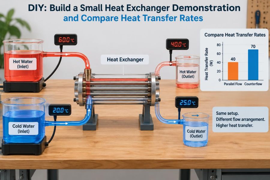
In co-current flow, both streams enter from the same end and move in the same general direction. In counter-current flow, they enter from opposite ends and move in opposite directions.
The physical exchanger can support both configurations if tubing connections are easy to swap. Label each port before testing. Accidentally changing the arrangement midway through a run makes a comparison meaningless.
| Arrangement | Temperature pattern | Typical teaching observation |
|---|---|---|
| Co-current | Both streams move toward a closer exit temperature | Driving force declines rapidly along the length |
| Counter-current | Hot and cold streams oppose each other | A more sustained driving force is often possible |
🌡️ Place temperature sensors where they answer the question
Measure all four stream temperatures: hot inlet, hot outlet, cold inlet, and cold outlet. Place sensors in well-mixed flowing regions, not pressed against a tube wall, where they may read wall temperature instead of bulk-fluid temperature.
For reservoir-fed systems, an inlet sensor close to the exchanger matters. Long exposed hoses can gain or lose heat before the fluid reaches the unit, making a reservoir reading an unreliable substitute.
⏱️ Measure flow rate instead of trusting a pump setting
A pump dial, voltage setting, or valve position is not a flow measurement. Determine volumetric flow by collecting discharge for a measured time and dividing volume by time:
V̇ = collected volume / collection timeFor water, mass flow rate is approximately density times volumetric flow rate. Near room temperature, 1 litre of water has a mass close to 1 kilogram, which is convenient for introductory work. Record units consistently: L/min is fine for collection, but convert to kg/s before calculating watts.
🧪 Run a leak and mixing check first
Before heating anything, circulate cool water through each side separately. Check every joint, inspect the outer shell, and confirm that flow exits only through its intended outlet.
Then inspect for cross-contamination. If water from one circuit enters the other, the experiment no longer represents heat transfer across a wall. A sudden unexplained reservoir-level change is a useful warning sign.
📏 Establish stable operating conditions
Fill the warm and cold reservoirs, begin circulation, and wait until inlet and outlet temperatures vary slowly. The exchanger itself has thermal mass, so early readings include energy used to warm or cool the copper, shell, and fittings.
A perfectly steady state is difficult with finite reservoirs, especially in a small setup. Aim for a short interval where readings are stable enough to average. Record whether reservoirs are recirculated, replenished, or once-through; the interpretation differs.
🗒️ Use a data sheet that prevents omissions
Create a row for each run before starting. At minimum, record arrangement, date, approximate ambient temperature, hot and cold flow rates, four temperatures, collection time, and observations such as visible bubbles or pump pulsing.
| Run | Flow pattern | Hot in/out | Cold in/out | Hot flow | Cold flow | Notes |
|---|---|---|---|---|---|---|
| 1 | Co-current | Record °C | Record °C | Record | Record | Leaks, bubbles, stability |
| 2 | Counter-current | Record °C | Record °C | Record | Record | Same target conditions |
Do not round temperatures aggressively while recording. Keep the instrument’s displayed precision, then round calculated results only to a sensible number of significant figures.
🔥 Calculate heat loss from the hot stream
For each run, calculate:
Q̇hot = ṁhot Cp (Th,in − Th,out)If hot water enters at 45 °C and leaves at 40 °C, its temperature drop is 5 K. The numerical difference in degrees Celsius and kelvin is the same for a temperature change.
This estimate represents energy leaving the hot stream. Some of it reaches the cold stream; some may escape through the exchanger wall, tubing, and exposed reservoir surfaces.
❄️ Calculate heat gained by the cold stream
Apply the same balance to the cold side:
Q̇cold = ṁcold Cp (Tc,out − Tc,in)In an ideal, insulated, steady exchanger, Q̇hot and Q̇cold would match. In a real demonstration, they often differ. Treat the gap as information to investigate rather than a result to hide.
⚖️ Reconcile the two heat-transfer estimates
A mismatch can arise from heat loss to the room, sensor calibration offsets, unsteady reservoirs, inaccurate flow measurement, or an incorrect sensor location. Small systems are particularly sensitive because exposed tubing has a large surface area compared with exchanger duty.
For a transparent report, show both values and state how you selected a comparison metric. You may use the smaller value as a conservative estimate of exchanged heat, or use their average only when the imbalance is modest and conditions are well characterized.
📈 Compare flow rate at constant inlet conditions
Run several trials with a fixed hot-side flow and approximately similar inlet temperatures while changing the cold-side flow. Plot heat-transfer rate against measured cold-side flow rate.
At very low cold flow, the cold stream can warm substantially but carries little mass per second. Raising flow often increases the heat capacity rate, ṁCp, and can improve shell-side convection. The measured heat duty may rise, then show diminishing gains as another resistance becomes limiting.
🌊 Understand why faster flow can help
Fluid near a wall moves more slowly than fluid in the central stream. This near-wall region resists heat transfer. Greater velocity can disturb and thin that thermal boundary layer, increasing the convection coefficient.
But “faster is better” is incomplete. Pumps require energy, pressure drop increases with flow, vibration can increase, and a small pump may produce unstable delivery. Engineering design weighs heat-transfer improvement against hydraulic cost.
🧭 Compare co-current and counter-current results fairly
For a flow-arrangement comparison, match hot and cold inlet temperatures and both flow rates as closely as practical. Let the unit stabilize after swapping connections, because switching lines may introduce air or change reservoir conditions.
Counter-current operation often provides a stronger average temperature driving force along an exchanger. It is therefore commonly favored when a close approach between one outlet temperature and the opposing inlet temperature is needed. Your compact coil may show only a subtle difference if heat losses and measurement uncertainty are large.
📐 Connect the experiment to UA and LMTD
A common exchanger relation is:
Q̇ = U A ΔTlmU is the overall heat-transfer coefficient, A is transfer area, and ΔTlm is the logarithmic mean temperature difference. This expression accounts for the fact that the temperature difference changes from one end of the exchanger to the other.
You do not need to calculate U for a first demonstration. Still, the equation provides a useful map: improve the fluid-side convection, wall conduction, area, or temperature driving force, and duty can increase—provided another resistance does not dominate.
🧩 Identify the thermal resistances in your model
Heat crosses several resistances in series: hot-side convection, copper-wall conduction, cold-side convection, and eventually any fouling layer. A simple resistance diagram is more useful than assuming copper conductivity alone determines performance.
Because copper is highly conductive, its wall resistance is often small compared with weak convection on either water side. That is why changing flow conditions can matter more than choosing slightly thicker or thinner copper tubing.
🧼 See fouling as a real operating problem
Fouling is the accumulation of scale, biological material, corrosion products, or process deposits on a heat-transfer surface. It adds thermal resistance and can narrow flow passages.
For a short water experiment, fouling is unlikely to develop meaningfully. However, a used coil with mineral deposits may perform differently from a clean one. In industrial service, cleaning access, allowable pressure drop, and expected deposit formation are part of exchanger selection.
🧊 Insulate strategically, not blindly
Wrap the main exchanger body and exposed hot-side tubing with removable insulation after completing an initial baseline run. Compare the hot-side and cold-side energy balances before and after insulation.
Insulation reduces unwanted heat exchange with the room, helping the measured stream-to-stream transfer dominate. Do not cover sensors or create bends that restrict hoses. Also remember that insulation may make leak inspection harder.
🚫 Avoid common experimental mistakes
- Using reservoir temperatures as exchanger inlet temperatures: hoses may change water temperature en route.
- Reading too early: startup transients are not representative of the intended operating condition.
- Changing several variables together: conclusions about cause and effect become weak.
- Ignoring air pockets: trapped air can reduce wetted area and make flow erratic.
- Assuming equal pump settings give equal flows: each circuit has different resistance.
- Forgetting units: mixing L/min with kg/s can inflate calculated duty dramatically.
A clean experiment is usually more valuable than a complicated one. A small number of repeatable runs teaches more than a large spreadsheet of uncontrolled readings.
🔍 Estimate uncertainty without pretending to know too much
Every temperature probe has finite accuracy and response time; every collected volume and timing measurement has error. When the temperature change is small, uncertainty in that difference can become large relative to the calculated heat duty.
Repeat a selected condition at least a few times and look at the spread. If repeated runs vary greatly, diagnose stability before making fine claims about design superiority. State that a difference is within experimental scatter when the data do not clearly separate the cases.
📊 Present results so the comparison is visible
Use a concise table for raw conditions and a graph for the main relationship. A graph of estimated heat-transfer rate versus cold-side flow rate is often more revealing than a page of individual readings.
Include both hot-side and cold-side heat estimates, or show their difference as an energy-balance check. Label configurations, units, and whether points represent repeated-run averages. Readers should be able to see what was held constant.
🛠️ Modify the apparatus one feature at a time
Once a baseline is established, test a purposeful change. Add coil length, alter coil spacing, install simple shell-side baffles, or compare insulated and uninsulated operation. Each modification should have a prediction before data are collected.
Baffles can force shell-side water across the coil rather than along an easy bypass route, potentially improving contact. They can also add pressure drop and create stagnant zones if poorly arranged. That balance is a miniature version of real exchanger design.
🧑🏫 Turn the build into a stronger learning exercise
Before running the system, ask participants to predict which outlet temperature changes when cold-side flow is increased and why. After the run, distinguish between a stream’s outlet temperature and total heat-transfer rate; they do not always move in the same direction.
For a design exercise, impose a constraint such as a fixed coil length or a limited pump capacity. Participants must then justify whether to spend effort on flow distribution, insulation, added area, or improved measurement quality.
🌍 Recognize the limits of this demonstration
This device does not represent high-pressure service, corrosive chemicals, phase change, sanitary validation, or industrial mechanical design. It cannot establish a universal heat-transfer coefficient because geometry, flow regime, insulation, and measurement methods strongly affect results.
It can, however, demonstrate the governing behavior honestly. Scaling up requires attention to materials compatibility, design pressure and temperature, codes, fouling allowance, cleanability, control response, maintenance, and detailed hydraulic calculations.
✅ The core lesson from a small exchanger
A heat exchanger is not judged only by how hot one outlet feels. Its performance depends on the rate at which each stream carries energy, the temperature difference available along the path, and the resistances between the fluids.
Your measurements connect these ideas directly. Flow rate changes the heat capacity rate and convection; counter-current routing can preserve driving force; insulation improves the energy balance; and repeated runs reveal whether an apparent improvement is actually trustworthy.
The most useful result is a defensible comparison: measured flow rates, well-placed temperatures, controlled conditions, and an explanation of why the observed heat-transfer rate changed.
Build modestly, measure patiently, and let the energy balance guide the conclusion. A coil of copper and two water streams can become a clear introduction to the decisions behind much larger thermal systems. 🧪🌡️🔄