
A pump operator increases a valve opening to raise the flow to a reactor. The flow responds, but then the reactor temperature begins to climb. Cooling water demand changes, vessel pressure shifts, and the liquid level in a downstream separator starts moving in the wrong direction.
No one action was necessarily wrong. The difficulty is that industrial equipment is connected: material, energy, pressure, composition, and inventory all move through the same plant at once. A process can appear calm at one measurement while another variable is quietly approaching an operating limit.
That is why the idea of one controller running an entire unit is usually misleading. A single control loop can hold one measured variable near one target, but a real process must meet several objectives simultaneously and respond to disturbances arriving at different locations and speeds.
Multiple control loops are not needless complexity. When designed well, they divide a complicated physical system into manageable jobs: keep material where it belongs, maintain stable flows, remove heat, protect equipment, and deliver product within specification.
🎛️ What a Control Loop Actually Does
A basic feedback control loop has four functional parts: a measurement, a controller, a final control element, and the process itself. A temperature transmitter measures a reactor temperature; a controller compares it with a setpoint; then it moves a cooling-water valve to reduce any difference.
The difference between measured value and setpoint is called the error. The controller continually calculates a response, often using proportional, integral, and derivative actions, commonly called PID control. Its purpose is not merely to move a valve, but to reject disturbances while keeping the variable stable.
🧭 One Plant, Many Variables to Manage
Most continuous processes have more than one controlled variable. Common examples include flow rate, liquid level, pressure, temperature, composition, pH, density, and product moisture. Batch operations also track profiles, endpoints, and timed additions.
Each variable represents a different physical need. Level prevents a vessel from emptying or overflowing. Pressure protects containment and affects phase behavior. Temperature influences heat transfer and reaction rate. Composition determines whether the product meets its required quality.
One loop cannot independently hold all of these measurements at their targets. It has only one control decision unless it is part of a larger coordinated architecture.
🔧 The Limited Number of Control Handles
Engineers call the quantity a controller changes a manipulated variable. It may be a valve position, pump speed, heater duty, agitator speed, reflux flow, or feed rate. These are the process “handles” available to the control system.
A useful first principle is that independent controlled objectives generally need enough independent manipulated variables to influence them. A jacketed reactor may use cooling-water flow to regulate temperature and an outlet valve to regulate level. Asking the cooling-water valve to regulate both at once creates a conflict.
The relationship is not always one-to-one, because variables interact. Still, this principle explains why adding measurements without providing meaningful control authority does not solve a control problem.
🌊 Material Balance Makes Level Control Necessary
Liquid level is an inventory variable. It follows a simple material-balance idea: if inflow exceeds outflow, level rises; if outflow exceeds inflow, level falls. A surge tank or separator can tolerate temporary imbalance, but not indefinitely.
Level loops often manipulate an outlet flow or inlet flow. Their job is usually to keep enough volume for reliable pumping and separation while avoiding overflow. They may be tuned more slowly than flow loops because the vessel itself provides storage capacity.
Without level control, a small persistent mismatch between streams eventually becomes an operational interruption. That interruption can propagate upstream and downstream through an entire plant.
💨 Pressure Is More Than a Safety Number
Pressure control is often associated with relief devices, but normal pressure control serves a different role. It maintains predictable vapor-liquid conditions, supports transfer between vessels, and can influence boiling temperature, gas density, and reaction behavior.
For example, a distillation column overhead pressure controller may adjust condenser duty or a vent valve. If pressure drifts, the column’s temperature profile and separation performance can change even when reflux and feed flows remain unchanged.
Relief valves protect against overpressure emergencies; they are not substitutes for a well-designed operating pressure loop. The normal control system should keep the process away from conditions that would challenge protective layers.
🌡️ Temperature Often Moves Chemistry and Quality
Temperature is frequently a quality and safety-critical variable because reaction rates, viscosity, solubility, vapor pressure, and equilibrium all depend on it. In an exothermic reactor, a modest increase can generate more heat, which may require faster heat removal.
A temperature loop therefore adjusts a heat-transfer path: steam flow, electrical heating power, cooling-water flow, refrigerant flow, or heat-exchanger bypass. The best manipulated variable depends on the process and on how quickly the utility can respond.
Temperature control alone does not guarantee quality. If feed composition changes or residence time shifts, the same temperature can produce a different outcome. This is one reason quality-related loops often sit above, or alongside, basic temperature control.
➡️ Flow Loops Create the Process Rhythm
Flow is usually the fastest and most direct variable to control. A flow controller receives a measurement from a flowmeter and adjusts a valve or pump speed to hold the requested rate despite changes in downstream pressure or valve friction.
Stable flow loops make the rest of the control structure more predictable. A reactor temperature controller can ask for more cooling-water flow only if a fast cooling-water flow loop reliably delivers it. Likewise, a ratio controller depends on each component flow being measured well.
For this reason, flow control is commonly treated as a foundational layer rather than an optional refinement.
🧪 Composition Control Faces a Measurement Challenge
Composition is often the variable that matters most commercially, but it can be difficult to measure continuously. Online analyzers may require sampling systems, calibration, maintenance, and minutes of transport or analysis delay.
When a direct composition signal is slow, operators may regulate related variables such as temperature, reflux ratio, density, conductivity, pH, or a calculated inferential estimate. These signals are useful only when their relationship to composition is understood over the operating range.
A temperature controller on a distillation tray, for instance, may help maintain product purity, but it is not automatically a purity measurement. Changes in pressure, feed quality, or hydraulics can weaken that correlation.
🪜 The Natural Hierarchy of Process Control
Industrial control systems often use layers. Fast loops stabilize local conditions; slower loops set the targets for those fast loops; optimization and production systems may sit above them. This hierarchy matches the different speeds of physical phenomena.
| Control layer | Typical purpose | Typical example |
|---|---|---|
| Regulatory | Reject local disturbances | Flow controller moves a valve |
| Supervisory | Coordinate regulatory loops | Temperature controller sets flow target |
| Optimization | Choose efficient operating targets | Adjust throughput within constraints |
The layers are not separate worlds. They must be designed so that the objectives at one level are achievable and do not undermine the safeguards at another.
🔗 Cascade Control Lets Fast Loops Do Fast Work
Cascade control uses one controller to set the setpoint of another. The outer, or primary, controller watches the important process variable. The inner, or secondary, controller handles a faster intermediate variable.
Consider reactor temperature control through a cooling-water valve. Rather than allowing the temperature controller to move the valve directly, it can set the target for a cooling-water flow controller. The flow loop quickly corrects for changes in water-supply pressure, while the temperature loop focuses on the slower thermal response.
Cascade is worthwhile only when the inner measurement responds earlier to relevant disturbances and the inner loop can be tuned substantially faster than the outer loop.
⚖️ Ratio Control Keeps Streams in Proportion
Many reactions, blends, and neutralization systems need streams maintained in a specified proportion. Ratio control measures a leading stream and calculates the setpoint for a following stream. If solvent flow rises, additive flow rises in proportion.
This is more reliable than setting two independent fixed flow targets when throughput changes. It preserves the intended recipe while allowing production rate to move.
Ratios should not be treated as chemistry guarantees. Meter bias, density variation, concentration changes, and poor mixing can mean that a correct volumetric ratio is still the wrong molar or mass ratio. Critical applications may need composition feedback to trim the ratio.
🧱 Feedforward Responds Before Error Appears
Feedback waits until a measured variable departs from its setpoint. Feedforward acts on a measured disturbance before that departure becomes large. A heat exchanger may adjust steam demand when cold-feed flow increases, rather than waiting for outlet temperature to fall.
Feedforward requires a believable process relationship and a disturbance that can be measured promptly. It is usually paired with feedback, not used alone, because the model will never be perfect and unmeasured disturbances still occur.
Think of it as anticipating a hill while cycling: you change effort as the slope begins, while still using your actual speed to correct any remaining error.
🧩 Process Interactions Create Conflicting Responses
In a multivariable process, one manipulated variable can affect several controlled variables. Raising reflux in a distillation column may improve one product composition while changing column pressure, tray temperatures, condenser load, and another product specification.
Interactions are why individually sensible loops can produce surprising plant behavior. Two controllers may both see an error and move their valves in ways that oppose each other or amplify a disturbance.
Engineers examine process gains, response directions, and time delays to decide which variables should be paired. The goal is not to eliminate all interaction, which is rarely possible, but to choose pairings that are strong and manageable.
🧮 When Multivariable Control Becomes Useful
For strongly coupled units, independent PID loops may not be sufficient. Decoupling methods, constraint controllers, and model predictive control can coordinate several manipulated and controlled variables together.
Model predictive control, or MPC, uses a dynamic model to predict future responses and select coordinated moves while respecting limits. It is often applied where delays, interactions, and operating constraints make manual loop coordination difficult.
Advanced control is not automatically better. It depends on adequate measurements, maintained models, clear objectives, and a stable regulatory control foundation. A poorly maintained analyzer or sticky valve can defeat sophisticated calculations.
⏱️ Different Process Speeds Demand Different Tuning
A pressure change in a gas header may be detected in seconds. A vessel level may drift over minutes. A large reactor temperature may respond over a much longer period. Controllers should not all be tuned with the same aggressiveness.
A fast loop should settle before a slower loop relies on it. In a cascade arrangement, this separation is particularly important. If the outer loop is as fast as the inner loop, both may chase the same disturbance and create oscillation.
Dead time also matters. A long sampling line, analyzer cycle, or transport delay makes aggressive feedback risky because the controller acts on information that is already old.
🌀 Mixing and Residence Time Can Hide the Real Problem
A sensor measures conditions at one location, not everywhere in a vessel. Inadequate mixing can create temperature, concentration, or pH gradients that the transmitter does not reveal. The loop may report a stable value while another zone is poorly controlled.
Residence-time distribution adds another complication. Material does not always spend the same amount of time in a tank, reactor, or column. Changes in holdup, flow pattern, or throughput can alter product behavior even when local setpoints are maintained.
Control design cannot repair a fundamentally unsuitable vessel, mixer, exchanger, or sensor location. Good instrumentation starts with understanding the physical process.
📍 Sensor Placement Determines What the Loop Sees
A temperature sensor immediately downstream of a steam injection point can see a different condition from a sensor after complete mixing. A pressure transmitter located across a restrictive line may include pressure drop that is irrelevant to the protected vessel.
Placement affects noise, lag, representativeness, maintainability, and safety. Sample points for analyzers need similar care: dead volume and plugging can turn a useful composition measurement into a delayed historical record.
Before changing tuning, ask whether the transmitter measures the variable that truly matters. This simple question prevents many fruitless adjustments.
🛠️ Final Control Elements Have Real Limits
Control valves have range limits, friction, backlash, stiction, and installed-flow characteristics. A valve that sticks and then jumps can produce cycling that looks like bad controller tuning. Pumps have minimum-flow needs, speed limits, and changing efficiency.
Valve sizing is especially consequential. An oversized valve may give excessive response to tiny position changes; an undersized valve may stay fully open while the process remains below target. Neither condition can be fixed solely in software.
Positioners, maintenance, and periodic performance checks are part of control quality. The control algorithm is only as capable as the actuator that implements its decision.
🚧 Constraints Must Override Economic Wishes
Every unit has boundaries: maximum pressure, minimum pump suction head, maximum temperature, valve travel limits, compressor surge margins, and environmental or product limits. Good control systems recognize these boundaries before a normal objective drives the process into them.
For example, a production-rate controller may increase feed until a compressor approaches its operating limit. A constraint strategy can hold throughput below that limit, even if an upstream target requests more production.
This is not a failure of optimization. It is the proper ordering of objectives: operate safely and reliably first, then pursue rate, energy efficiency, or yield within the available operating window.
🛡️ Basic Control Is Not the Same as Safety Protection
Normal control loops are designed to regulate routine disturbances. Independent protective functions may be needed for dangerous deviations, including alarms, interlocks, trips, relief systems, and emergency shutdown functions.
A high-temperature alarm should alert an operator; a separate trip may shut off reactants or heating if temperature reaches a defined hazardous condition. The appropriate protection depends on hazard analysis, process dynamics, equipment design, and applicable site practices.
It is unsafe to assume a single PID loop will always respond correctly during instrument failure, utility loss, runaway chemistry, or a major equipment malfunction. Control and safeguarding must be considered together, but they have distinct roles.
🏭 Example: A Jacketed Continuous Reactor
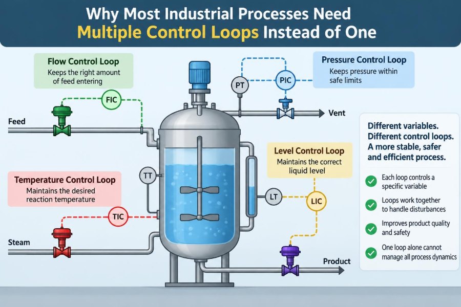
A hypothetical continuous stirred-tank reactor illustrates why several loops coexist. Feed flow determines throughput, reactant ratio influences stoichiometry, reactor level maintains inventory, jacket flow removes heat, pressure manages vapor behavior, and a quality measurement or laboratory result verifies conversion or selectivity.
- A feed-flow loop holds the production rate.
- A ratio loop sets the second reactant flow from the first.
- A level loop adjusts outlet flow.
- A cascade temperature-to-jacket-flow loop rejects utility disturbances.
- A pressure loop controls a vent or condenser duty where appropriate.
These loops are not duplicates. Each closes a different physical balance or manages a different operational objective. Their setpoints must still be coordinated, especially when production rate changes.
🧪 Example: Distillation Needs Coordinated Objectives
A distillation column must manage feed, reflux, reboiler heat, overhead pressure, bottoms level, reflux-drum level, and product quality. The available handles are limited, and many of them interact.
A common regulatory structure assigns level loops to distillate and bottoms flows, pressure control to condenser duty or venting, and flow control to reflux and steam. Product composition or tray temperature controllers may then adjust reflux or boil-up targets.
The exact arrangement varies with the separation, equipment, and constraints. What matters is the logic: inventory loops keep the column operable, fast utility and flow loops stabilize responses, and quality loops make slower corrections to achieve specification.
💧 Example: pH Control Is Deceptively Difficult
Neutralization looks simple—measure pH and add acid or base—but the pH scale is logarithmic. Near neutrality, a small reagent addition can cause a large pH change, while buffering and mixing can delay the visible response.
A practical system may include controlled influent flow, reagent flow control, an agitated tank for mixing, pH feedback that trims reagent demand, and sometimes feedforward from influent flow or known acidity. Split-range valves may use acid in one direction and base in the other.
Probe condition matters greatly. Fouling, coating, aging, and poor calibration can cause a controller to make confident but incorrect adjustments.
👩💻 Operators Need a Process Story, Not a Screen Full of Numbers
Multiple loops help only when people can understand their purpose. Displays should show key measurements, setpoints, controller modes, valve outputs, limits, and the relationships between loops. An operator needs to know whether a temperature controller is directly moving a valve or setting a flow-loop target.
Clear alarm design is equally important. During a disturbance, dozens of consequence alarms can obscure the initiating problem. Rational alarm priorities and meaningful messages support timely action.
Operating procedures should explain expected responses to startup, shutdown, utility changes, analyzer failure, manual operation, and loop handover. Human understanding remains essential when the process deviates from normal assumptions.
🔄 Manual, Automatic, and Bumpless Transfer
Controllers are sometimes placed in manual during commissioning, maintenance, abnormal operation, or troubleshooting. A sudden transfer back to automatic can cause a valve jump if the controller output does not match the current manual position.
Bumpless transfer aligns the controller state so that switching modes does not create an unnecessary process upset. Integral action also needs protection against windup when an output is saturated at a limit.
These details may sound minor, but they matter in tightly coupled systems. A sudden steam-valve movement can disturb pressure, temperature, and downstream flow at the same time.
📈 Performance Monitoring Reveals Loops That Quietly Degrade
A loop can remain in automatic while performing poorly. Frequent oscillation, long periods at output limits, excessive manual operation, noisy measurements, or slow recovery after routine disturbances are useful warning signs.
Monitoring should distinguish process variability from equipment problems. A cycling level may result from interacting upstream flow loops; a cycling flow loop may result from valve stiction; a noisy measurement may reflect installation rather than process instability.
Maintenance and control engineers benefit from reviewing trends together. The trend history often shows the sequence of cause and effect more clearly than a snapshot alarm list.
⚠️ Common Mistake: Tuning Each Loop in Isolation
Changing one controller at a time is sensible during initial testing, but tuning a loop without considering its neighbors can create trouble later. A very aggressive level controller may impose rapid flow changes that upset a downstream pressure or composition loop.
Start with the fastest, most local loops, then tune outer and slower loops after their inner loops are stable. Test realistic disturbances, not only setpoint changes. A loop that tracks a setpoint neatly may still reject feed or utility disturbances poorly.
Documenting normal controller modes, tuning changes, and observed interactions makes future troubleshooting far more efficient.
🧱 Common Mistake: Adding Complexity Before Fixing Basics
When a process is unstable, it is tempting to add another controller, an advanced algorithm, or a new calculated signal. Sometimes that is appropriate, but first verify fundamentals: transmitter health, signal scaling, valve action, sensor location, utility capacity, process design, and controller mode.
A cascade loop cannot compensate for a plugged cooling-water strainer. An optimizer cannot create capacity beyond a fully open valve. A composition controller cannot overcome an analyzer sample system that no longer represents the process.
Complexity should solve a defined problem with a clear mechanism, not conceal an unexamined one.
🗺️ A Practical Design Sequence for Multiple Loops
A structured approach reduces the chance of building contradictory loops. Begin with process understanding and hazards, then identify objectives, disturbances, measurements, manipulated variables, constraints, and response times.
- Map material and energy balances for each unit.
- Define operating limits and independent protective needs.
- Establish reliable regulatory loops for flow, level, pressure, and temperature.
- Assess interactions and choose sensible variable pairings.
- Add cascade, ratio, feedforward, or multivariable strategies only where they address a real limitation.
- Commission gradually, test disturbances, and monitor performance after startup.
This sequence is iterative. Plant data often reveal delays or interactions that were not fully apparent in design calculations.
🎯 The Core Principle: Divide Control by Physical Job
Most industrial processes need multiple loops because they have multiple balances, multiple disturbances, multiple time scales, and multiple constraints. A flow loop cannot reliably serve as a level, temperature, pressure, and quality controller merely because all of those variables are connected.
The strongest designs assign each loop a clear physical job, coordinate their setpoints in a hierarchy, and recognize the limits of sensors, valves, and models. More loops are not inherently better; the right loops, properly coordinated and maintained, make complex processes controllable.
Industrial control works best when each loop manages a distinct part of the process while the overall system keeps those parts moving toward the same safe operating objective. That is how a plant turns many interacting disturbances into stable, repeatable operation. 🧪⚙️📈