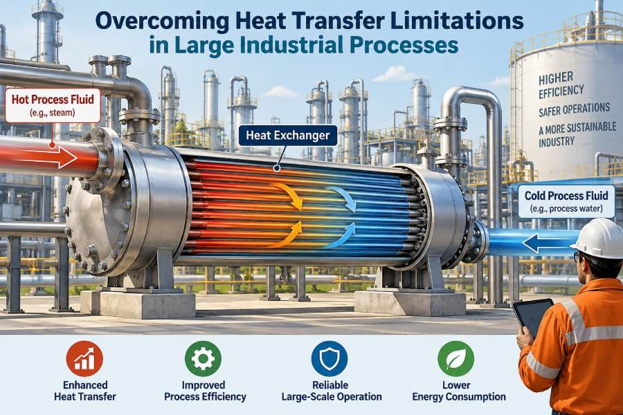

A production line can look stable on a process diagram while struggling in the field. A reactor may be receiving enough utility steam, a dryer may be supplied with hot air, and a heat exchanger may appear correctly sized—yet throughput remains constrained, temperatures drift, or energy consumption climbs.
These problems become more visible as equipment scales up. Heat must travel farther, flow distribution becomes less even, surfaces foul over time, and a small temperature shortfall can affect thousands of kilograms of material per hour.
For students, heat transfer limitations connect textbook equations to real equipment behavior. For working professionals, they often explain why a plant cannot safely reach its expected rate, why quality varies from batch to batch, or why a seemingly simple debottlenecking project becomes complicated.
The central challenge is not merely “adding more heat.” It is moving the required heat to the right place, at the right rate, with an acceptable temperature driving force and without creating safety, reliability, or product-quality problems.
🔥 Heat Transfer as a Rate Problem
Heat transfer is the movement of thermal energy caused by a temperature difference. In industry, the total duty may be large, but the decisive question is usually the rate: can enough energy cross the available boundary in the available residence time?
A useful starting relationship for a heat exchanger is Q = U A ΔTlm. Here, Q is heat-transfer rate, U is the overall heat-transfer coefficient, A is area, and ΔTlm is the log-mean temperature difference, a representative driving force across the exchanger.
If any of these terms falls, duty falls. Large processes expose the practical constraints behind each term: limited surface area, poor fluid-side coefficients, reduced driving force, or resistance created by deposits and walls.
🏭 Why Scale Changes the Problem
Scale is not neutral. As a vessel grows, its volume rises faster than its surface area. For geometrically similar equipment, volume scales with length cubed, while surface area scales with length squared.
This means a larger reactor has less heat-transfer area available per unit volume unless designers deliberately add internal coils, jackets, external recirculation loops, or other surfaces. The result can be slower heating, slower cooling, and larger internal temperature differences.
A small laboratory vessel may be heated quickly from its wall because every portion of liquid is close to that wall. A large vessel with the same general shape may need vigorous mixing and added heat-transfer surface to avoid a long, uneven thermal response.
📏 The Resistance Network Behind Overall U
The overall coefficient U combines several thermal resistances. Heat may need to cross a hot-fluid film, a tube wall, a cold-fluid film, and fouling layers on either side.
It is useful to picture these as electrical resistors in series. One high resistance can dominate the entire system, even if every other component is well designed.
- Film resistance: resistance in the fluid layer next to a surface.
- Wall resistance: conduction through metal, polymer, ceramic, or lining.
- Fouling resistance: deposits, corrosion products, biological growth, scale, coke, or product films.
- Contact resistance: imperfect contact between joined solids, relevant in some equipment and assemblies.
Improving a non-dominant resistance may produce little practical gain. A sound troubleshooting effort identifies the controlling resistance before selecting a remedy.
🌡️ Temperature Driving Force Is Not the Same as Temperature
A high utility temperature does not automatically create a high exchanger duty. What matters is the temperature difference between the two streams at each location along the exchanger.
When a process stream approaches the utility temperature, the local driving force shrinks. This “pinch” is common near the outlet of a heater or cooler and can limit performance even when the inlet temperature difference looks generous.
For sensible heating and cooling, counter-current flow usually maintains a more useful driving force than co-current flow. In counter-current operation, the hot and cold streams enter from opposite ends, allowing closer outlet approaches under many conditions.
🔄 Phase Change Can Help—and Complicate—Design
Condensing steam and boiling refrigerants transfer substantial energy at nearly constant temperature. This can provide a stable driving force and a high heat-transfer coefficient, which is why phase-change utilities are widely used.
However, phase change introduces its own limits. Condensate must drain without backing up, non-condensable gases must be removed, and boiling surfaces must avoid unstable vapor blanketing or dryout.
In an evaporator, excessive vapor generation can reduce liquid wetting on heat-transfer surfaces. In a steam heater, trapped air can act as insulation. The utility may be available, but the interface that should transfer heat is no longer functioning well.
🧱 Conduction Limits in Thick Walls and Linings
Metals such as carbon steel and many alloys conduct heat reasonably well, so wall resistance is often modest in clean metal exchangers. It becomes more significant when walls are thick, materials have low thermal conductivity, or protective linings are required.
Refractory-lined furnaces, glass-lined reactors, polymer-lined piping, and corrosion-resistant coatings are common examples. These materials may be essential for containment or chemical compatibility, yet they can slow thermal response.
Designers must balance heat transfer against mechanical strength, corrosion allowance, pressure containment, and cleanability. Choosing the most conductive wall material is rarely the only requirement.
🌊 Fluid Films Often Control Performance
At a solid surface, fluid motion slows because of the no-slip condition. Heat must cross this thin region, often called the thermal boundary layer. A stagnant or poorly renewed boundary layer creates high resistance.
Turbulent flow disrupts and renews the boundary layer, generally increasing the convective heat-transfer coefficient. Laminar flow, especially with viscous liquids, produces thicker thermal layers and lower coefficients.
This is why two fluids with similar bulk temperatures can behave very differently. Water moving rapidly through a tube may transfer heat efficiently, while a viscous syrup moving slowly may be limited by the film next to the wall.
🌀 Mixing Is a Heat-Transfer Tool
Agitation does more than keep solids suspended. In jacketed tanks and coil-heated reactors, it carries material from the vessel interior to the heat-transfer surface and reduces temperature gradients in the bulk liquid.
Poor mixing can create a misleading average temperature. A sensor near the wall may report the target value while a cold, viscous zone remains near the vessel center—or a hot zone near a coil may damage a temperature-sensitive product.
Impeller selection, baffles, liquid level, viscosity, gas sparging, and impeller speed all affect circulation. More power is not always the answer; the aim is a circulation pattern that reaches poorly mixed regions.
🧪 Viscosity Creates a Double Penalty
Viscous fluids are difficult because they often flow slowly near heat-transfer surfaces and mix poorly in large vessels. Both effects lower convective heat transfer.
Many materials also become much more viscous as they cool. A cooling duty can therefore become progressively harder: as the product temperature falls, the fluid-side coefficient falls as well.
Examples include polymers, concentrated food products, slurries, heavy oils, and crystallizing solutions. Equipment designed using properties at a warm, low-viscosity condition may disappoint at the cold end of the process.
🧊 Fouling Turns Design Margin into Lost Capacity
Fouling is the accumulation of unwanted material on heat-transfer surfaces. Its effect is twofold: it adds thermal resistance and can narrow flow passages, changing pressure drop and flow distribution.
Common fouling mechanisms include mineral scale, particulate deposition, crystallization, polymer films, corrosion products, biological deposits, and coke formation. The mechanism matters because cleaning and prevention methods are different.
A gradual rise in utility use, longer batch heating time, increasing pressure drop, or failure to reach a target outlet temperature may indicate fouling. These signals should be interpreted alongside changes in feed rate, composition, and operating conditions.
🧼 Cleaning Strategy Must Match the Deposit
Cleaning-in-place may use circulation, chemical detergents, acids, alkalis, oxidants, or rinses, depending on the equipment and deposit. Mechanical methods such as brushing, pigging, hydroblasting, or tube cleaning can also be appropriate.
The wrong cleaning approach can be ineffective or damaging. For example, aggressive chemistry may harm gaskets, passivation layers, or sensitive alloys, while an incomplete rinse can introduce a new contamination risk.
Effective programs define when cleaning is triggered, how success is verified, and which operating data are retained. Cleaning only after production is severely limited often costs more than planned intervention based on performance trends.
📉 Pressure Drop Is the Trade-Off Nobody Can Ignore
Increasing velocity often improves convection, but it also increases pressure drop. That raises pumping or compression energy and may exceed available pressure or mechanical limits.
High velocity can additionally cause erosion, vibration, or damage to fragile solids. Low velocity reduces energy use but may worsen fouling, maldistribution, or laminar-flow resistance.
The best design is not the one with the highest heat-transfer coefficient. It is the one that meets duty, operability, cleaning, reliability, and energy requirements over its expected operating range.
🧭 Flow Arrangement Shapes the Available Duty
Shell-and-tube exchangers, plate exchangers, spiral exchangers, air coolers, scraped-surface units, and compact exchangers each create different flow patterns. Their performance depends not just on area, but on how streams are guided across that area.
Shell-and-tube equipment is robust and flexible, but shell-side bypassing or poor baffle design can reduce effective heat transfer. Plate exchangers offer high coefficients in many liquid services, yet narrow passages may be unsuitable for fibrous, fouling, or large-particle fluids.
Equipment selection should start with the process fluid, duty profile, fouling tendency, pressure, allowable pressure drop, maintenance access, and required temperature approach—not with a preferred exchanger type.
🧩 Maldistribution Wastes Installed Surface Area
In large exchangers, flow rarely divides perfectly among all channels, tubes, or distributor paths. Some passages may receive too much flow while others receive too little.
Low-flow regions contribute less heat transfer and may foul faster. High-flow regions can have excessive pressure drop, erosion, or vibration. The average flow rate may look acceptable while local behavior is not.
Headers, nozzles, distributor design, channel geometry, orientation, and manufacturing tolerances all matter. Large systems need careful attention to inlet and outlet details, not only the core heat-transfer surface.
🧯 Hot Spots and Cold Spots Affect More Than Energy Use
Temperature nonuniformity can alter reaction selectivity, crystallization behavior, viscosity, drying rate, and product stability. In exothermic reactors, a local hot spot can accelerate reaction rates and create a hazardous feedback loop.
In heat-sensitive products, a hot wall may cause discoloration, degradation, or coking even when the bulk outlet temperature is acceptable. In freezing or crystallizing services, a cold spot can initiate deposits that further reduce local heat transfer.
Bulk temperature is therefore an incomplete measure of thermal performance. Where consequences are significant, engineers need to consider local wall temperatures, mixing quality, and spatial temperature patterns.
⚗️ Exothermic Reactors Face a Scaling Constraint
Reactions that release heat require a removal path that can keep up with heat generation. As reactor scale increases, available surface area per reactor volume typically declines, while the reaction inventory grows.
This does not mean large exothermic reactors are inherently unsafe. It means heat removal must be designed as a primary process function, using jackets, internal coils, external recirculation exchangers, staged feeds, dilution, temperature control, and appropriate relief design.
Reaction kinetics can be strongly temperature dependent. A modest local temperature rise may increase the generation rate while heat removal remains limited, so transient scenarios deserve as much attention as steady operation.
🧨 Endothermic Processes Need Reliable Heat Delivery
Endothermic reactions absorb heat. If heat cannot reach the reacting zone fast enough, conversion may fall and temperature profiles may become uneven.
Steam reforming, calcination, thermal cracking, and many drying or evaporation operations illustrate the issue, although each has different equipment and chemistry. External furnace heat must cross tube walls; internal heating must be distributed without obstructing flow or creating excessive wall temperatures.
In these services, raising the external temperature may increase heat flux, but it can also increase material stress, promote coke formation, or damage catalyst and product. The process limit may be metallurgical or chemical rather than simply thermal.
💨 Gas-Side Heat Transfer Is Frequently the Bottleneck
Gases have relatively low density and heat capacity per unit volume, and their convective coefficients are often lower than those of liquids. Air coolers, dryers, furnaces, and gas-gas exchangers therefore commonly need substantial area or enhanced surfaces.
Fins increase area on the gas side, where the resistance is often greatest. But fins can collect dust, become blocked, or suffer corrosion, reducing their benefit over time.
For an air cooler, ambient temperature, recirculation of warm discharge air, fan performance, and fin cleanliness can all limit duty. A process engineer should avoid treating “air temperature” as the only relevant variable.
🌬️ Utility Limitations Can Masquerade as Equipment Failure
A poorly performing exchanger is not always the exchanger’s fault. Steam pressure may be lower than expected, cooling-water temperature may rise seasonally, chilled-water capacity may be shared with other users, or refrigerant systems may be constrained.
Utility-side measurements should include supply and return temperatures, pressures, flow rates where practical, control-valve positions, and condensate behavior. A fully open steam valve, for example, may reveal insufficient available pressure, an undersized valve, or a downstream restriction.
Checking the utility system early prevents unnecessary exchanger replacement and reveals whether the true bottleneck lies outside the process unit.
🎛️ Control Loops Cannot Create Missing Heat Capacity
Temperature control can stabilize a process only within the physical capacity of the heating or cooling system. When a utility valve remains nearly fully open and the temperature still misses its target, the issue is likely a capacity limitation rather than poor controller tuning.
That said, poor tuning can amplify fluctuations. Dead time, sensor location, valve stiction, nonlinear utility behavior, and changing process gain make thermal loops challenging, particularly in large vessels with long response times.
A useful distinction is this: control tuning improves how the system uses available capacity; equipment changes increase the capacity itself. Both may be needed, but they solve different problems.
📍 Instrumentation Must Represent the Process
One temperature sensor measures one location, not an entire vessel or exchanger. Sensor placement can conceal gradients, especially in stratified tanks, large ducts, multiphase equipment, and poorly mixed reactors.
Flow measurement errors can also distort heat-balance calculations. A calculated exchanger duty depends on flow rate and temperature difference, so uncertainty in either measurement affects the conclusion.
Useful diagnostic instruments may include multiple temperature points, differential-pressure transmitters, utility flow measurement, vibration monitoring, and occasional thermal imaging where surfaces are accessible and interpretation is appropriate.
🧮 Heat Balances Turn Complaints into Evidence
A heat balance compares energy lost by the hot stream with energy gained by the cold stream, allowing for reasonable uncertainty and possible heat losses. It is one of the most practical ways to investigate underperformance.
For a single-phase stream, an approximate duty is Q = ṁ Cp ΔT, where ṁ is mass flow rate and Cp is heat capacity. Phase changes, reactions, and changing compositions require additional terms.
If independently calculated hot- and cold-side duties disagree greatly, first question the data: flow meters, sample properties, sensor calibration, bypasses, and unmeasured streams. Do not force a conclusion from an untrustworthy balance.
🔍 A Structured Troubleshooting Sequence
Random adjustments often make a heat-transfer problem harder to diagnose. A disciplined sequence separates changing operating conditions from genuine equipment degradation.
- Define the shortfall: target, actual performance, timing, and operating mode.
- Verify measurements and establish a credible heat balance.
- Compare current flows, temperatures, pressures, and compositions with a suitable reference condition.
- Check utility availability, valve positions, condensate removal, and bypasses.
- Review pressure-drop trends, fouling history, and recent cleaning results.
- Assess flow distribution, mixing, and likely local temperature behavior.
- Choose the lowest-risk correction that addresses the controlling limitation.
This approach does not eliminate engineering judgment, but it prevents a common failure mode: treating the most visible symptom rather than the limiting mechanism.
🛠️ Increasing Area Is One Option, Not the First Reflex
Adding exchanger area can increase duty, but it may involve cost, plot-space limitations, support modifications, piping changes, added hold-up, and new control challenges. It is most valuable when analysis shows that area is truly limiting.
Alternatives include cleaning, raising a feasible utility temperature, improving mixing, rearranging flow to counter-current service, reducing bypassing, using a more suitable exchanger geometry, or lowering process resistance through formulation or operating changes.
For a hypothetical viscous batch process, replacing an ineffective jacket alone with a jacket plus an external recirculation loop may improve both surface area and fluid movement. The better result comes from addressing two linked limits, not from area alone.
⚡ Intensification Can Shrink Thermal Resistance
Process intensification means achieving a required function with more effective transport, smaller equipment, or better integration. For heat transfer, this can involve compact exchangers, corrugated plates, static mixers, microstructured devices, rotating surfaces, or scraped-surface exchangers.
These technologies can provide high surface-area-to-volume ratios and stronger mixing. They are not universal upgrades: narrow passages may foul, pressure drop can be high, maintenance may be specialized, and scale-up experience may be limited for a given service.
The right question is not whether equipment is “advanced,” but whether its transport benefits match the fluid, duty, reliability expectations, and maintenance capability of the plant.
♻️ Heat Integration Reduces Utility Demand
Sometimes the best way to overcome a utility limitation is to recover heat already present in the process. A hot product stream may preheat a feed, or a warm condensate stream may supply low-temperature heating elsewhere.
Heat integration must respect temperature levels. Heat at a modest temperature cannot perform a high-temperature duty without a heat pump, mechanical vapor recompression, or another energy input.
Pinch analysis is a structured method for identifying realistic heat-recovery opportunities across a process. It helps distinguish recoverable heat from heat that is energetically present but too low in temperature to be useful for a proposed duty.
🧱 Materials and Mechanical Limits Set Boundaries
Higher temperatures, pressures, velocities, and thermal cycling can stress equipment. Tube vibration, gasket limits, differential expansion, creep at elevated temperature, corrosion, and thermal fatigue may constrain an apparently attractive performance increase.
Rapid temperature changes deserve particular caution. Thick-walled equipment and dissimilar materials can develop internal temperature gradients that create mechanical stress even when the average temperature remains within design limits.
Any modification that changes utility conditions or operating envelopes should be reviewed through the plant’s established engineering, mechanical integrity, and process-safety processes. Thermal improvements should not trade away containment or reliability.
🛡️ Safety Depends on Transient Behavior
Steady-state duty calculations are necessary, but many serious thermal challenges occur during startup, shutdown, utility loss, blocked flow, feed interruption, or an unexpected reaction change.
For exothermic systems, loss of cooling may reduce heat removal while reaction heat continues. For heated systems, loss of circulation can expose stagnant material to high wall temperatures. These scenarios may require interlocks, alarms, emergency quench arrangements, relief systems, or conservative operating procedures.
Safeguards should be based on a clear understanding of the process response and should be maintained and tested according to site practices. A heat-transfer improvement is incomplete if abnormal operation remains poorly understood.
📈 Monitor Trends Instead of Waiting for Failure
Useful performance indicators include exchanger approach temperature, calculated overall coefficient, pressure drop, heating or cooling time, utility consumption, valve position, and product temperature variability.
A single indicator rarely proves a cause. A falling calculated U together with rising pressure drop may support a fouling hypothesis; a stable pressure drop with lower duty may point instead to utility conditions, flow reduction, or measurement error.
Trend data becomes more valuable when it is tied to cleaning events, feed changes, ambient conditions, and production rate. This turns routine records into a basis for predictive maintenance and better operating decisions.
🚫 Common Responses That Miss the Real Constraint
Several intuitive fixes can fail because they treat heat transfer as a one-variable problem.
- Raising utility temperature: may increase duty but can damage product, increase fouling, or exceed material limits.
- Increasing pump speed: may improve convection but create excessive pressure drop, erosion, or cavitation risk.
- Retuning the controller: may reduce oscillation but cannot compensate for inadequate area or utility capacity.
- Adding area without cleaning: can leave the underlying fouling mechanism untouched.
- Using average temperature alone: can miss damaging local hot spots or cold zones.
Each action can be valid in the right context. The mistake is applying it before identifying the dominant resistance and operational constraint.
🧠 Designing for the Real Operating Envelope
Heat-transfer equipment should not be judged only at one nominal design point. Feed properties, throughput, ambient conditions, utility availability, fouling state, batch level, and product specifications change over time.
Design cases should include expected difficult conditions, such as cold cooling water, maximum viscosity, end-of-run fouling, turndown operation, and startup. These cases often reveal whether installed margin is useful or merely theoretical.
For existing plants, the same mindset supports debottlenecking. A proposed change should be tested against upstream and downstream effects: pumping capacity, utility headers, control valves, separators, relief systems, and product-quality limits.
✅ The Core Principle: Manage the Whole Thermal System
Large industrial heat-transfer problems are rarely solved by focusing on a single equation or a single piece of equipment. They arise from the interaction of driving force, area, resistances, flow behavior, utilities, controls, materials, and time-dependent operation.
The most reliable path is to establish a credible heat balance, identify the dominant resistance or constraint, evaluate the trade-offs of possible changes, and verify the result with operating data. That method applies equally to a fouled exchanger, a slow batch reactor, a constrained evaporator, or a high-temperature furnace.
Good thermal engineering is therefore a systems discipline. It recognizes that maximum heat flux is not always the objective; safe, controllable, maintainable heat transfer at the required process conditions is.
When large processes struggle thermally, the winning response is to diagnose the real bottleneck and improve the complete heat-transfer path—not simply to turn up the heat. 🧪🔥🏭