The calculation of compressible flow through orifice plates at high dP (critical flow) appears to be carried out incorrectly in most instances. This flow condition is often encountered on gas plants, compressor stations and pipelines where orifice plates are commonly used as a cheap and convenient way to regulate blowdown and pressurising rates. Blowdown must be achieved within the time period required to make the plant safe but at the same time without an excessive rate of pressure drop that could damage equipment. A more accurate calculation method is proposed below and should be used to improve the engineering predictions.
Orifice flow calculations typically use the following equations or some variant of them:
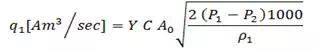 | Crane Eq. 2-24 / Eq. (1) |
| Crane Eq. 2-23 / Eq. (2) |
Where subscript “1” indicates upstream conditions, subscript “2” indicates downstream conditions and Ao is the orifice cross section area.
For metering applications the ASME equation is often used to determine the Expansion Factor Y:
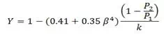 | Eq. (3) |
for flange taps, where P and T are in absolute units.
For high accuracy metering (e.g. AGA 3) use of these calculations is often limited to ![]() .
.
 | Eq. (4) |
where P and T are in absolute units.
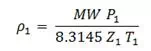
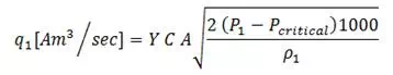
It is then often assumed that the orifice flow goes critical (i.e. sonic velocity) at P2 = 0.528 x P1 (for air) and the choked flow equation is then applied:
 | Eq. (5) |
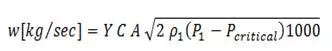 | Eq. (6) |
(Crane Pg 2-15), where Pcr = 0.528 x P1
For P2 less than Pcr this method assumes that the flow does not increase further.


Comments are closed