The general function of a heat exchanger is to transfer heat from one fluid to another. The basic component of a heat exchanger can be viewed as a tube with one fluid running through it and another fluid flowing by on the outside. There are thus three heat transfer operations that need to be described:
1) Convective heat transfer from fluid to the inner wall of the tube
2) Conductive heat transfer through the tube wall
3) Convective heat transfer from the outer tube wall to the outside fluid
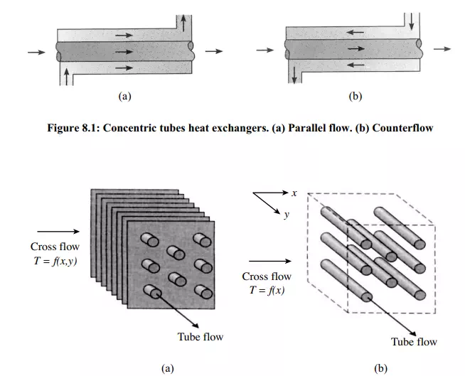
Heat exchangers are typically classified according to flow arrangement and type of construction. The simplest heat exchanger is one for which the hot and cold fluids move in the same or opposite directions in a concentric tube (or double-pipe) construction. In the parallel-flow arrangement of Figure 8.1a, the hot and cold fluids enter at the same end, flow in the same direction, and leave at the same end. In the counterflow arrangement of Figure 8.1b, the fluids enter at opposite ends, flow in opposite directions, and leave at opposite ends. Alternatively, the fluids may be in cross flow (perpendicular to each other), as shown by the finned and unfinned tubular heat exchangers of Figure 8.2.
The two configurations differ according to whether the fluid moving over the tubes is unmixed or mixed. In Figure 8.2a, the fluid is said to be unmixed because the fins prevent motion in a direction (y) that is transverse to the main-flow direction (x). In this case the fluid temperature varies with x and y. In contrast, for the unfinned tube bundle of Figure 8.2b, fluid motion, hence mixing, in the transverse direction is possible, and temperature variations are primarily in the main-flow direction. Since the tube flow is unmixed, both fluids are unmixed in the finned exchanger, while one fluid is mixed and the other unmixed in the unfinned exchanger.
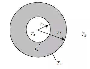
To develop the methodology for heat exchanger analysis and design, we look at the problem of heat transfer from a fluid inside a tube to another fluid outside.
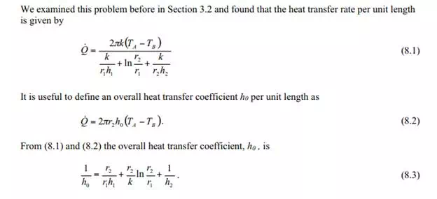
We will make use of this in what follows. A schematic of a counterflow heat exchanger is shown in Figure 8.4. We wish to know the temperature distribution along the tube and the amount of heat transferred.