There are two terms one is called NPSH R and the other NPSH A.
R stands for required, it is given by the manufacturer and is determined based on the experimental data.
A is for available and is calculated and cross verified by smart engineers like you.
But why do we need this data? For obvious reasons as to avoid the cavitation by making sure that at a given flow rate with a particular impeller dia size, yourNPSH A is greater than the NPSH R.
● For every flow capacity, there’s a different NPSH R, and it increases with a square of a capacity.
● Pump manufacturers make sure that for each flow capacity, there’s anNPSH, which is found experimentally.
● Flow capacity is an independent variable when plotted flow, head, efficiency, and NPSH. This NPSH that is found is called NPSH R.
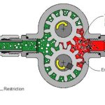
● The pump manufacturer set up a system where the fluid, water, is passed through the system.
● The flow rate and speed are kept constant while the pressure of the suction line is reduced (as shown in the video above).
● As the pressure is keep reducing there will be a point when the pressure in the suction line reduces to vapor pressure and ultimately lower than that of vapor pressure. This pressure, meter of liquid head, is called NPSH R.
1. As the flow capacity is increased, head reduces, and the NPSH R increases.
2. There are other factors also like, impeller size, at a given flow rate theNPSH R increases with the decrease in the dia of an impeller.
3. The curve that is developed is somewhat in a “U” shape; that implies that it’s minimum at the mid-range capacity flow.
The tank was at 6 m above the pump suction nozzle. The pressure inside the tank was 10 psi g, and the liquid in the tank was at bubble point.
Specific gravity 0.58 ; Density of the fluid = 1000 kg/m3 x 0.58 = 580 kg/m3,
implies P = ρgh = 5 psi g and hence, the pressure measured at the suction line was 15 psi g. The total pressure of (15 psi g + 14.7 psi a) 29.7 psi a.
The vapor pressure of the fluid = The total pressure in absolute = 24.7 psi a (10 psi g + 14.7 psi a)
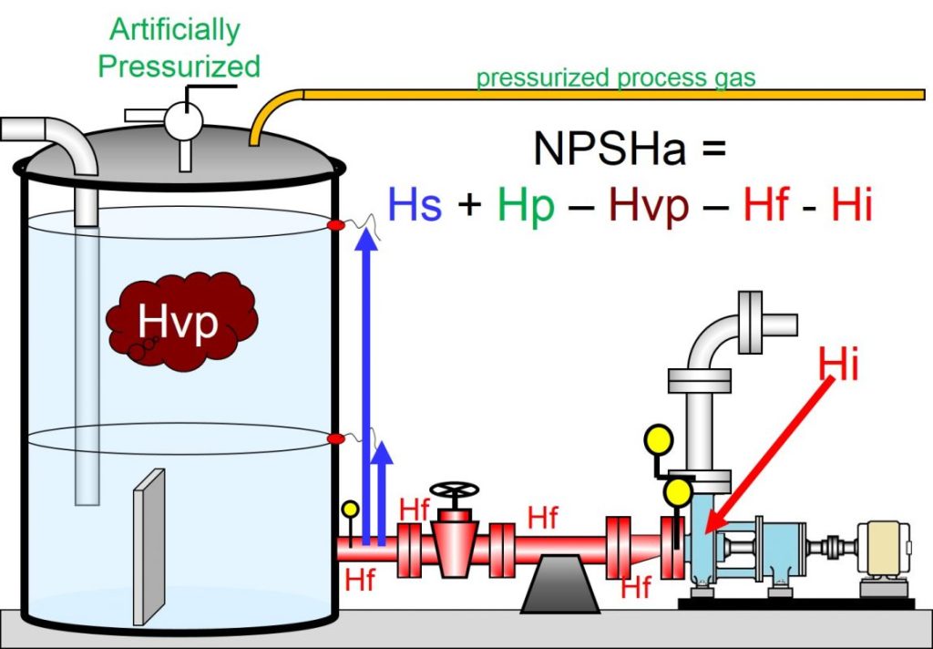
Now let’s calculate the NPSH available (NPSH A) =
Total pressure at the suction – Vapor pressure of the liquid – Pressure drop across the suction line
If for the time being you neglect the pressure drop across the line and fittings the resultant would be:
29.7 – 24.7 = 5.0 psi a
So far you haven’t minus the pressure drop that is inside the line and fittings.
If you convert this 5 psi a, into meter liquid head it would be near about 6 m.
Additionally, you haven’t deducted the pressure drop across the suction line, but if you do it will result in NPSH A as 5 m or lesser than that.
Okay, I see the problem, there, NPSH A was less than that of NPSH R.
Yes. But there’s something more. There’s a twist.
The problem was that calculated NPSH available (NPSH A) was 5 psi a without the pressure drop in the suction line. That means you need additional head to avoid cavitation.
But one thing that nobody told you about pump cavitation and perhaps no one will ever, Starting NPSH.
Starting NPSH?
Yes, the NPSH R that we are talking about is called running NPSH, something like running torque and starting NPSH as starting torque.
That means you need additional NPSH to start the pump than that of required for running pump. That means, today’s case,
● The NPSH R for 5 m3/hr was 6 m
● The NPSH A that we calculated without friction loss was 6 m
● Moreover, you need additional head, when you are starting the pump, called starting NPSH
So the actual value of NPSH A, which we just calculated, was not sufficient enough to the addition of
1. running NPSH,
2. the frictional loss in the line,
3. starting NPSH.