Since packed columns consist of shaped particles contained within a column, their behaviour will in many ways be similar to that of packed beds which have already
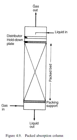
been considered. There are, however, several important differences which make the direct application of the equations for pressure gradient difficult. First, the size of the packing elements in the column will generally be very much larger and the Reynolds number will therefore be such that the flow is turbulent. Secondly, the packing elements will normally be hollow, and therefore have a large amount of internal surface which will offer a higher flow resistance than their external surface. The shapes too are specially designed to produce good mass transfer characteristics with relatively small pressure gradients. Although some of the general principles already discussed can be used to predict pressure gradient as a function of flowrate, it is necessary to rely heavily on the literature issued by the manufacturers of the packings. In general, packed towers are used for bringing two phases in contact with one another and there will be strong interaction between the fluids. Normally one of the fluids will preferentially wet the packing and will flow as a film over its surface; the second fluid then passes through the remaining volume of the column. With gas (or vapour)–liquid systems, the liquid will normally be the wetting fluid and the gas or vapour will rise through the column making close contact with the down-flowing liquid and having little direct contact with the packing elements. An example of the liquid–gas system is an absorption process where a soluble gas is scrubbed from a mixture of gases by means of a liquid, as shownin Figure 4.9. In a packed column used for distillation, the more volatile component of, say, a binary mixture is progressively transferred to the vapour phase and the less volatile condenses out in the liquid. Packed columns have also been used extensively for liquid–liquid extraction processes where a solute is transferred from one solvent to another, as discussed in Chapter 12. Some principles involved in the design and operation of packed columns will be illustrated by considering columns for gas absorption. In this chapter an outline of the construction of the column and the flow characteristics will be dealt with, whereas the magnitude of the mass transfer coefficients is discussed later in Chapters 11, 12, and 13. The full design process is discussed in Volume 6. In order to obtain a good rate of transfer per unit volume of the tower, a packing is selected which will promote a high interfacial area between the two phases and a high degree of turbulence in the fluids. Usually increased area and turbulence are achieved at the expense of increased capital cost and/or pressure drop, and a balance must be made between these factors when arriving at an economic design.
General description
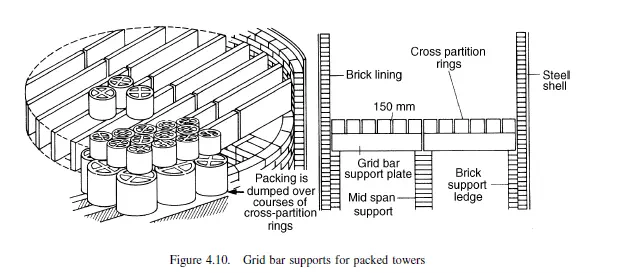
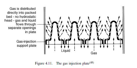
The construction of packed towers is relatively straightforward. The shell of the column may be constructed from metal, ceramics, glass, or plastics material, or from metal with a corrosion-resistant lining. The column should be mounted truly vertically to help uniform liquid distribution. Detailed information on the mechanical design and mounting of industrial scale column shells is given by BROWNELL and YOUNG(45), MOLYNEUX(46) and in BS 5500(47), as well as in Volume 6. The bed of packing rests on a support plate which should be designed to have at least 75 per cent free area for the passage of the gas so as to offer as low a resistance as possible. The simplest support is a grid with relatively widely spaced bars on which a few layers of large Raschig or partition rings are stacked. One such arrangement is shown in Figure 4.10. The gas injection plate described by LEVA(48) shown in Figure 4.11 is designed to provide separate passageways for gas and liquid so that they need not vie for
passage through the same opening. This is achieved by providing the gas inlets to the bed at a point above the level at which liquid leaves the bed.
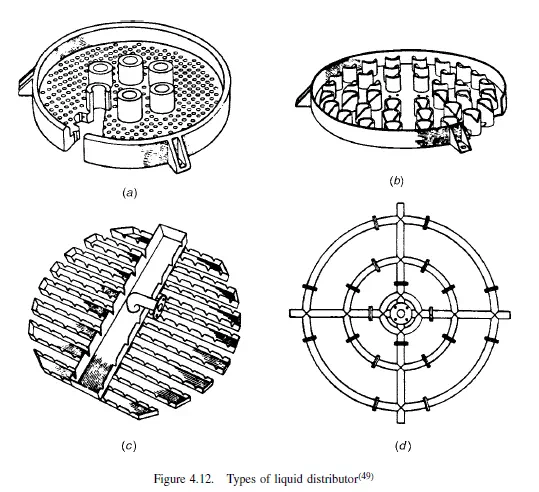
At the top of the packed bed a liquid distributor of suitable design provides for the uniform irrigation of the packing which is necessary for satisfactory operation. Four examples of different distributors are shown in Figure 4.12(49), and may be described as follows:
a) A simple orifice type which gives very fine distribution though it must be correctly sized for a particular duty and should not be used where there is any risk of the
holes plugging
b) The notched chimney type of distributor, which has a good range of flexibility for the medium and upper flowrates, and is not prone to blockage
c) The notched trough distributor which is specially suitable for the larger sizes of tower, and, because of its large free area, it is also suitable for the higher gas rates
d) The perforated ring type of distributor for use with absorption columns where high gas rates and relatively small liquid rates are encountered.
This type is especially suitable where pressure loss must be minimised. For the larger size of tower, where installation through manholes is necessary, it may be made up in flanged sections.
Uniform liquid flow is essential if the best use is to be made of the packing and, if the tower is high, re-distributing plates are necessary. These plates are needed at intervals of about 212 –3 column diameters for Raschig rings and about 5–10 column diameters for Pall rings, but are usually not more than 6 m apart(50). A “hold-down” plate is often placed at the top of a packed column to minimise movement and breakage of the packing caused by surges in flowrates. The gas inlet should also be designed for uniform flow over the cross-section and the gas exit should be separate from the liquid inlet. Further details on internal fittings are given by LEVA(48). Columns for both absorption and distillation vary in diameter from about 25 mm for small laboratory purposes to over 4.5 m for large industrial operations; these industrial columns may be 30 m or more in height. Columns may operate at pressures ranging from high vacuum to high pressure, the optimum pressure depending on both the chemical and
the physical properties of the system.
Packings
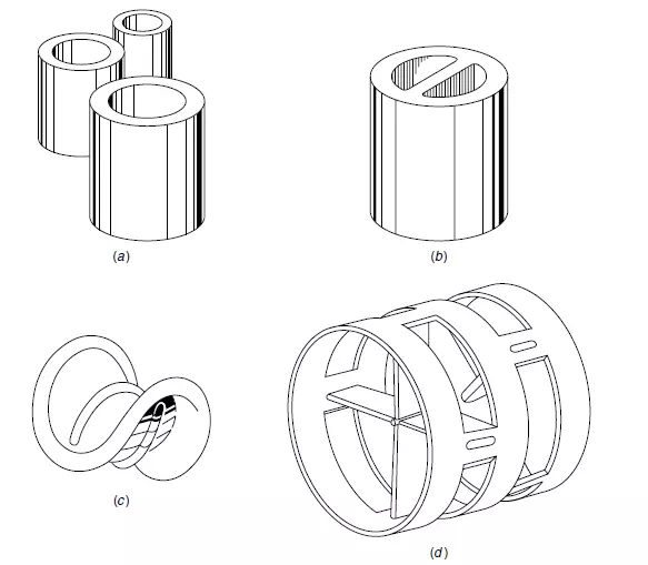
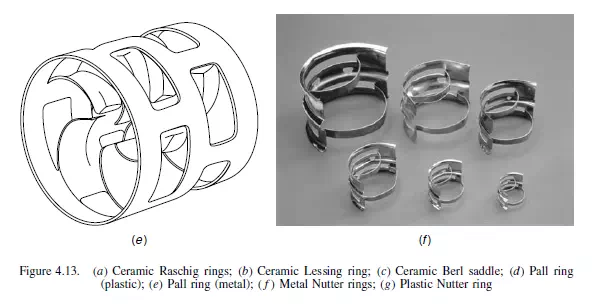
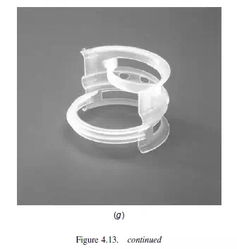
Packings can be divided into four main classes—broken solids, shaped packings, grids,and structured packings. Broken solids are the cheapest form and are used in sizes from about 10 mm to 100 mm according to the size of the column. Although they frequently form a good corrosion-resistant material they are not as satisfactory as shaped packings either in regard to liquid flow or to effective surface offered for transfer. The packing should be of as uniform size as possible so as to produce a bed of uniform characteristics with a desired voidage. The most commonly used packings are Raschig rings, Pall rings, Lessing rings, and Berl saddles. Newer packings include Nutter rings, Intalox and Intalox metal saddles, Hy-Pak, and Mini rings and, because of their high performance characteristics and low pressure drop, these packings now account for a large share of the market. Commonly used packing elements are illustrated in Figure 4.13. Most of these packings are available in a wide range of materials such as ceramics, metals, glass, plastics, carbon, and sometimes rubber. Ceramic packings are resistant to corrosion and comparatively cheap, but are heavy and may require a stronger packing support and foundations. The smaller metal rings are also available made from wire mesh, and these give much-improved transfer characteristics in small columns.
A non-porous solid should be used if there is any risk of crystal formation in the pores when the packing dries, as this can give rise to serious damage to the packing elements. However, some plastics are not very good because they are not wetted by many liquids. Channelling, that is non-uniform distribution of liquid across the column cross-section, is much less marked with shaped packings, and their resistance to flow is much less. Shaped packings also give a more effective surface per unit volume because surface contacts are reduced to a minimum and the film flow is much improved compared with broken solids. On the other hand, the shaped packings are more expensive, particularly when small sizes are used. The voidage obtainable with these packings varies from about 0.45 to 0.95. Ring packings are either dumped into a tower, dropped in small quantities, or may be individually stacked if 75 mm or larger in size. To obtain high and uniform voidage and to prevent breakage, it is often found better to dump the packings into a tower full of liquid. Stacked packings, as shown in Figure 4.10, have the advantage that the flow channels are vertical and there is much less tendency for the liquid to flow to the walls than with
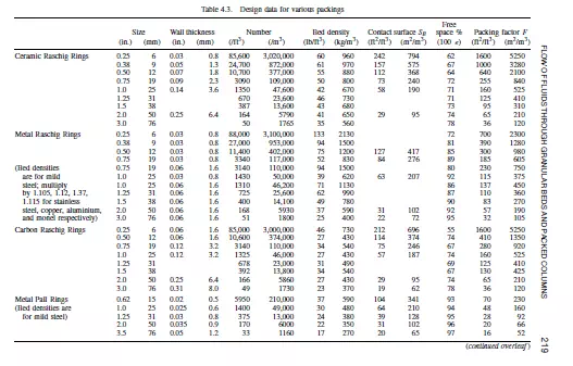
random packings. The properties of some commonly used industrial packings are shown in Table 4.3. The size of packing used influences the height and diameter of a column, the pressure drop and cost of packing. Generally, as the packing size is increased, the cost per unit volume of packing and the pressure drop per unit height of packing are reduced, and the mass transfer efficiency is reduced. Reduced mass transfer efficiency results in a taller column being needed, so that the overall column cost is not always reduced by increasing the packing size. Normally, in a column in which the packing is randomly arranged, the packing size should not exceed one-eighth of the column diameter. Above this size, liquid distribution, and hence the mass transfer efficiency, deteriorates rapidly. Since cost per unit volume of packing does not fall much for sizes above 50 mm whereas efficiency continues to fall, there is seldom any advantage in using packings much larger than 50 mm in a randomly packed column.
For laboratory purposes a number of special packings have been developed which are, in general, too expensive for large diameter towers. Dixon packings, which are Lessing rings made from wire mesh, and KnitMesh, a fine wire mesh packing, are typical examples. These packings give very high interfacial areas and, if they are flooded with liquid before operation, all of the surface is active so that the transfer characteristics are very good even at low liquid rates. The volume of liquid held up in such a packing is low and the pressure drop is also low. Some of these high efficiency woven wire packings have been used in columns up to 500 mm diameter. Grid packings, which are relatively easy to fabricate, are usually used in columns of square section, and frequently in cooling towers which are described in Volume 1, Chapter 13. They may be made from wood, plastics, carbon, or ceramic materials, and, because of the relatively large spaces between the individual grids, they give low pressure
drops. Further advantages lie in their ease of assembly, their ability to accept fluids with

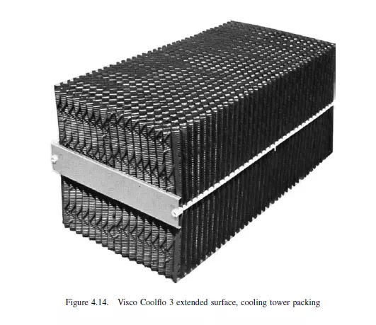
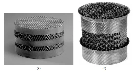
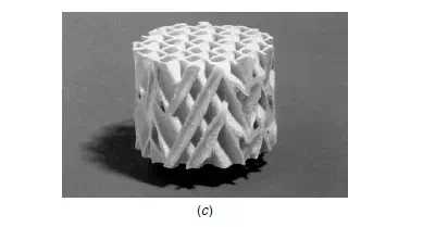
suspended solids, and their ease of wetting even at very low liquid rates. The main problem is that of obtaining good liquid distribution since, at high liquid rates, the liquid tends to cascade from one grid to the next without being broken up into fine droplets which are desirable for a high interfacial surface. An example of a cooling tower packing, ‘Coolflo 3’(51) is shown in Figure 4.14. This is similar to the structured packings described later, and consists of vacuum formed PVC sheets clamped together within a metal and plastics frame to form a module which can be 0.6 m or 1.2 m in depth. Structured packings may be broadly classified into either the knitted or the non-knitted type, and both types may be assembled in a segmented way or in a spiral form. In the latter, corrugated strips or ribbons coil about a centre axis to form a flat cake of the requisite tower diameter which is usually less than 1 m. These elements are then stacked one upon the other to provide the necessary bed depth. In the rigid type of structured packing, these corrugated sheets of metal or plastic are assembled to form intersecting open channels. The sheets may, in addition, be perforated and they provide uniform liquid flow over both sides while vapour flows upwards and provides intimate contact with the liquid. One such type of packing, Mellapak(52) is shown in Figure 4.15, and others such as Gempak(53) are also available. Low pressure drops of typically 50 N/m2 per theoretical stage are possible with HETP’s, discussed in Chapters 10 and 11, ranging from 0.2 to 0.6 m, voidages in excess of 95 per cent, and high specific surface areas. The resulting higher capacity and efficiency with
structured packings is, however, achieved at higher initial capital cost than with the other packings discussed in this section(54).