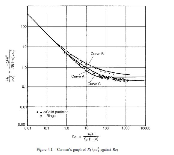
Equation 4.9 applies to streamline flow conditions, though CARMAN(7) and others have extended the analogy with pipe flow to cover both streamline and turbulent flow conditions through packed beds. In this treatment a modified friction factor R1/ρu21 is plotted against a modified Reynolds number Re1. This is analogous to plotting R/ρu2 against Re for flow through a pipe as in Volume 1, Chapter 3. The modified Reynolds number Re1 is obtained by taking the same velocity and characteristic linear dimension d_m as were used in deriving equation 4.9. Thus:
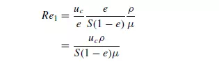
The friction factor, which is plotted against the modified Reynolds number, is R1/ρu21, where R1 is the component of the drag force per unit area of particle surface in the
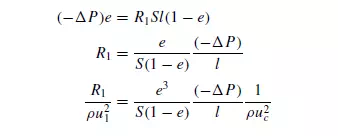
direction of motion. R1 can be related to the properties of the bed and pressure gradient as follows. Considering the forces acting on the fluid in a bed of unit cross-sectional
area and thickness l, the volume of particles in the bed is l(1 − e) and therefore the total surface is Sl(1 − e). Thus the resistance force is R1Sl(1 − e). This force on the fluid must be equal to that produced by a pressure difference of _P across the bed. Then, since the free cross-section of fluid is equal to e:
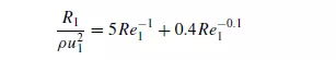
Carman found that when R1/ρu21 was plotted against Re1 using logarithmic coordinates, his data for the flow through randomly packed beds of solid particles could be correlated approximately by a single curve (curve A, Figure 4.1), whose general equation is:
The form of equation 4.16 is similar to that of equation 4.17 proposed by FORCHHEIMER(8) who suggested that the resistance to flow should be considered in two parts: that due to the viscous drag at the surface of the particles, and that due to loss in turbulent eddies and at the sudden changes in the cross-section of the channels. Thus:

The first term in this equation will predominate at low rates of flow where the losses are mainly attributable to skin friction, and the second term will become significant at high flowrates and in very thin beds where the enlargement and contraction losses become very important. At very high flowrates the effects of viscous forces are negligible.
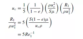
From equation 4.16 it can be seen that for values of Re1 less than about 2, the second term is small and, approximately:

Equation 4.18 can be obtained from equation 4.11 by substituting for −_P/l from equation 4.15. This gives:
As the value of Re1 increases from about 2 to 100, the second term in equation 4.16 becomes more significant and the slope of the plot gradually changes from −1.0 to about
−14. Above Re1 of 100 the plot is approximately linear. The change from complete streamline flow to complete turbulent flow is very gradual because flow conditions are
not the same in all the pores. Thus, the flow starts to become turbulent in the larger pores, and subsequently in successively smaller pores as the value of Re1 increases. It
is probable that the flow never becomes completely turbulent since some of the passages may be so small that streamline conditions prevail even at high flowrates. Rings, which as described later are often used in industrial packed columns, tend to deviate from the generalised curve A on Figure 4.1 particularly at high values of Re1.
SAWISTOWSKI(9) compared the results obtained for flow of fluids through beds of hollow packings (discussed later) and has noted that equation 4.16 gives a consistently low result for these materials. He proposed:

This equation is plotted as curve B in Figure 4.1. For flow through ring packings which as described later are often used in industrial packed columns, ERGUN(10) obtained a good semi-empirical correlation for pressure drop as follows:
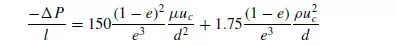
Writing d = 6/S (from equation 4.3):
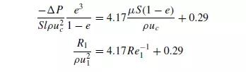
This equation is plotted as curve C in Figure 4.1. The form of equation 4.21 is somewhat similar to that of equations 4.16 and 4.17, in that the first term represents viscous losses which are most significant at low velocities and the second term represents kinetic energy losses which become more significant at high velocities. The equation is thus applicable over a wide range of velocities and was found by Ergun to correlate experimental data well for values of Re1/(1 − e) from 1 to over 2000. The form of the above equations suggests that the only properties of the bed on which the pressure gradient depends are its specific surface S (or particle size d) and its voidage e. However, the structure of the bed depends additionally on the particle size distribution, the particle shape and the way in which the bed has been formed; in addition both the
walls of the container and the nature of the bed support can considerably affect the way the particles pack. It would be expected, therefore, that experimentally determined values of pressure gradient would show a considerable scatter relative to the values predicted by the equations. The importance of some of these factors is discussed in the next section. Furthermore, the rheology of the fluid is important in determining how it flows through a packed bed. Only Newtonian fluid behaviour has been considered hitherto. For non-Newtonian fluids, the effect of continual changes in the shape and cross-section of the flow passages may be considerable and no simple relation may exist between pressure gradient and flowrate. This problem has been the subject of extensive studies by several workers including KEMBLOWSKI et al.(11). In some applications, there may be simultaneous flow of two immiscible liquids, or of a liquid and a gas. In general, one of the liquids (or the liquid in the case of liquid–gas systems) will preferentially wet the particles and flow as a continuous film over the surface of the particles, while the other phase flows through the remaining free space. The problem
is complex and the exact nature of the flow depends on the physical properties of the two phases, including their surface tensions. An analysis has been made by several workers including BOTSET(12) and GLASER and LITT(13).