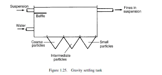
The settling tank
Material is introduced in suspension into a tank containing a relatively large volume of water moving at a low velocity, as shown in Figure 1.25. The particles soon enter the
slowly moving water and, because the small particles settle at a lower rate, they are carried further forward before they reach the bottom of the tank. The very fine particles
are carried away in the liquid overflow. Receptacles at various distances from the inlet collect different grades of particles according to their terminal falling velocities, with the particles of high terminal falling velocity collecting near the inlet. The positions at which the particles are collected may be calculated on the assumption that they rapidly reach their terminal falling velocities, and attain the same horizontal velocity as the fluid.
If the material is introduced in solid form down a chute, the position at which the particles are deposited will be determined by the rate at which they lose the horizontal
component of their velocities. The larger particles will therefore be carried further forward and the smaller particles will be deposited near the inlet. The position at which the particles are deposited may be calculated using the relations given in Chapter 3.
The elutriator
Material may be separated by means of an elutriator, which consists of a vertical tube up which fluid is passed at a controlled velocity. The particles are introduced, often through a side tube, and the smaller particles are carried over in the fluid stream while the large particles settle against the upward current. Further size fractions may be collected if the overflow from the first tube is passed vertically upwards through a second tube of greater cross-section, and any number of such tubes can be arranged in series.
The Spitzkasten
This plant consists of a series of vessels of conical shape arranged in series. A suspension of the material is fed into the top of the first vessel and the larger particles settle, while the smaller ones are carried over in the liquid overflow and enter the top of a second conical vessel of greater cross-sectional area. The bases of the vessels are fitted with wide diameter outlets, and a stream of water can be introduced near the outlet so that the particles have to settle against a slowly rising stream of liquid. The size of the smallest particle which is collected in each of the vessels is influenced by the upward velocity at the bottom outlet of each of the vessels. The size of each successive vessel is increased, partly because the amount of liquid to be handled includes all the water used for classifying in the previous vessels, and partly because it is desired to reduce, in stages, the surface velocity of the fluid flowing from one vessel to the next. The Spitzkasten thus combines the principles used in the settling tank and in the elutriator. The size of the material collected in each of the units is determined by the rate of feeding of suspension, the upward velocity of the liquid in the vessel and the diameter of the vessel. The equipment can also be used for separating a mixture of materials into its constituents, provided that the size range is not large. The individual units can be made of wood or sheet metal. The Hydrosizer, illustrated in Figure 1.26, works on the same principle although it has a number of compartments trapezoidal in section. It is suitable for use with materials finer
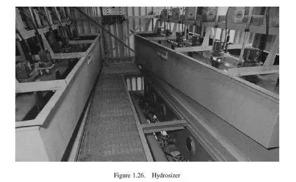
than about 4-mesh (ca. 5 mm) and it works at high concentrations in order to obtain the advantages of hindered settling. Altogether eight sharply classified fractions are produced, ranging from coarse nearest to the feed inlet to fine from the eighth compartment, at feed rates in the range 2–15 kg/s.
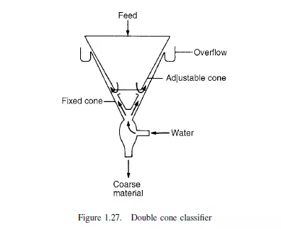
The double cone classifier
This classifier, shown in Figure 1.27, consists of a conical vessel, with a second hollow cone of greater angle arranged apex downwards inside it, so that there is an annular space of approximately constant cross-section between the two cones. The bottom portion of the inner cone is cut away and its position relative to the outer cone can be regulated by a screw adjustment. Water is passed in an upward direction, as in the Spitzkasten, and overflows into a launder arranged round the whole of the periphery of the outer cone. The material to be separated is fed in suspension to the centre of the inner cone, and the liquid level is maintained slightly higher than the overflow level, so that there is a continuous flow of liquid downwards in the centre cone. The particles are therefore brought into the annular space where they are subjected to a classifying action; the smaller particles are carried away in the overflow, and the larger particles settle against the liquid stream and are taken off at the bottom.
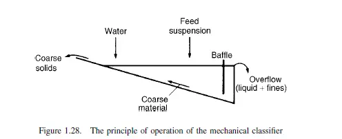
The mechanical classifier
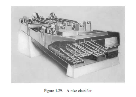
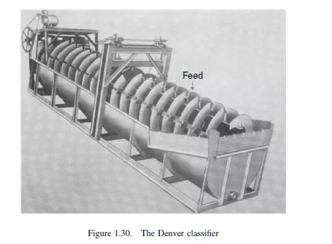
Several forms of classifier exist in which the material of lower settling velocity is carried away in a liquid overflow, and the material of higher settling velocity is deposited on the bottom of the equipment and is dragged upwards against the flow of the liquid, by some mechanical means. During the course of the raking action, the solids are turned over so that any small particles trapped under larger ones are brought to the top again. The mechanical classifier is extensively used where it is necessary to separate a large amount of fines from the oversize material. Arrangement of a number of mechanical classifiers in series makes it possible for a material to be separated into several size fractions. In the rake classifier, which consists of a shallow rectangular tank inclined to the horizontal, the feed is introduced in the form of a suspension near the middle of the tank and water for classifying is added at the upper end, as shown in Figure 1.28. The liquid, together with the material of low terminal falling velocity, flows down the tank under a baffle and is then discharged over an overflow weir. The heavy material settles to the bottom and is then dragged upwards by means of a rake. It is thus separated from the liquid and is discharged at the upper end of the tank. Figure 1.29 shows the Dorr–Oliver rake classifier. Figure 1.30 shows the Denver classifier which is similar in action although a trough is used which is semicircular in cross-section, and the material which settles to
the bottom is continuously moved to the upper end by means of a rotating helical scraper.
The bowl classifier
The bowl classifier, which is used for fine materials, consists of a shallow bowl with a concave bottom as shown in Figure 1.31. The suspension is fed into the centre of the
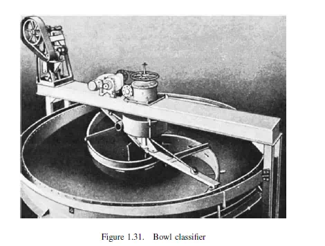
bowl near the liquid surface, and the liquid and the fine particles are carried in a radial direction and pass into the overflow which is an open launder running round the whole of the periphery of the bowl at the top. The heavier or larger material settles to the bottom and is raked towards the outlet at the centre. The classifier has a large overflow area, and consequently high volumetric rates of flow of liquid may be used without producing a high linear velocity at the overflow. The action is similar to that of a thickener which is effecting incomplete clarification.
The hydraulic jig
The hydraulic jig operates by allowing material to settle for brief periods so that the particles do not attain their terminal falling velocities, and is therefore suitable for
separating materials of wide size range into their constituents. The material to be separated is fed dry, or more usually in suspension, over a screen and is subjected to a pulsating action by liquid which is set in oscillation by means of a reciprocating plunger. The particles on the screen constitute a suspension of high concentration and therefore the advantages of hindered settling are obtained. The jig usually consists of a rectangularsection tank with a tapered bottom, divided into two portions by a vertical baffle. In one section, the plunger operates in a vertical direction; the other incorporates the screen over which the separation is carried out. In addition, a stream of liquid is fed to the jig during the upward stroke. The particles on the screen are brought into suspension during the downward stroke of the plunger (Figure 1.32a). As the water passes upwards the bed opens up, starting at the top, and thus tends to rise en masse. During the upward stroke the input of water is adjusted so that there is virtually no flow through the bed (Figure 1.32b). During this period differential settling takes place and the denser material tends to collect near the screen and the lighter material above it. After a short time the material becomes divided into three strata, the bottom layer consisting of the large particles of the heavy material, the next of large particles of the lighter material together with small particles of the heavy material, and the top stratum of small particles of the light material. Large particles wedge at an earlier stage than small ones and therefore the small particles of the denser material
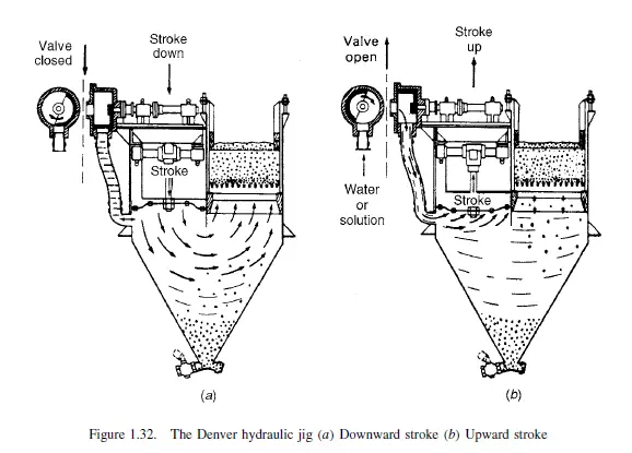
are able to fall through the spaces between the larger particles of the light material. Many of these small particles then fall through the supporting gauze. Four separate fractions are obtained from the jig and the successful operation of the plant depends on their rapid removal. The small particles of the heavy material which have fallen through the gauze are taken off at the bottom of the tank. The larger particles of each of the materials are retained on the gauze in two layers, the denser material at the bottom and the less dense material on top. These two fractions are removed through gates at the side of the jig. The remaining material, consisting of small particles of the
lighter material, is carried away in the liquid overflow.
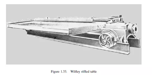
Riffled tables
The riffled table, of which the Wilfley table shown in Figure 1.33 is a typical example, consists of a flat table which is inclined at an angle of about 3◦ to the horizontal. Running approximately parallel to the top edge is a series of slats, or riffles as they are termed, about 6 mm in height. The material to be separated is fed on to one of the top corners and a reciprocating motion, consisting of a slow movement in the forward direction and a very rapid return stroke, causes it to move across the table. The particles also tend to move downwards under the combined action of gravity and of a stream of water which is introduced along the top edge, but are opposed by the riffles behind which the smaller particles or the denser material tend to be held. Thus, the large particles and the less dense material are carried downwards, and the remainder is carried parallel to the riffles. In many cases, each riffle is tapered, with the result that a number of fractions can be collected. Riffled tables can be used for separating materials down to about 50 μm in size, provided that the difference in the densities is large.