INTRODUCTION
Processes for the separation of particles of various sizes and shapes often depend on the variation in the behaviour of the particles when they are subjected to the action of a
moving fluid. Further, many of the methods for the determination of the sizes of particles in the sub-sieve ranges involve relative motion between the particles and a fluid.
The flow problems considered in Volume 1 are unidirectional, with the fluid flowing along a pipe or channel, and the effect of an obstruction is discussed only in so far as it
causes an alteration in the forward velocity of the fluid. In this chapter, the force exerted on a body as a result of the flow of fluid past it is considered and, as the fluid is generally diverted all round it, the resulting three-dimensional flow is more complex. The flow of fluid relative to an infinitely long cylinder, a spherical particle and a non-spherical particle is considered, followed by a discussion of the motion of particles in both gravitational and centrifugal fields.
FLOW PAST A CYLINDER AND A SPHERE
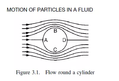
The flow of fluid past an infinitely long cylinder, in a direction perpendicular to its axis, is considered in the first instance because this involves only two-directional flow, with no flow parallel to the axis. For a non-viscous fluid flowing past a cylinder, as shown in Figure 3.1, the velocity and direction of flow varies round the circumference. Thus at A and D the fluid is brought to rest and at B and C the velocity is at a maximum. Since the fluid is non-viscous, there is no drag, and an infinite velocity gradient exists at the surface of the cylinder. If the fluid is incompressible and the cylinder is small, the sum of the kinetic energy and the pressure energy is constant at all points on the surface. The kinetic energy is a maximum at B and C and zero at A and D, so that the pressure falls from A to B and from A to C and rises again from B to D and from C to D; the pressure at A and D being the same. No net force is therefore exerted by the fluid on the cylinder. It is found that, although the predicted pressure variation for a non-viscous fluid agrees well with the results obtained with a viscous fluid over the front face, very considerable differences occur at the rear face. It is shown in Volume 1, Chapter 11 that, when a viscous fluid flows over a surface, the fluid is retarded in the boundary layer which is formed near the surface and that the boundary layer increases in thickness with increase in distance from the leading edge. If the pressure is falling in the direction of flow, the retardation of the fluid is less and the
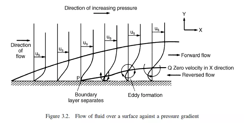
boundary layer is thinner in consequence. If the pressure is rising, however, there will be a greater retardation and the thickness of the boundary layer increases more rapidly. The force acting on the fluid at some point in the boundary layer may then be sufficient to bring it to rest or to cause flow in the reverse direction with the result that an eddy current is set up. A region of reverse flow then exists near the surface where the boundary layer has separated as shown in Figure 3.2. The velocity rises from zero at the surface to a maximum negative value and falls again to zero. It then increases in the positive direction until it reaches the main stream velocity at the edge of the boundary layer, as shown in Figure 3.2. At PQ the velocity in the X-direction is zero and the direction of flow in the eddies must be in the Y -direction.
For the flow of a viscous fluid past the cylinder, the pressure decreases from A to B and from A to C so that the boundary layer is thin and the flow is similar to that
obtained with a non-viscous fluid. From B to D and from C to D the pressure is rising and therefore the boundary layer rapidly thickens with the result that it tends to separate from the surface. If separation occurs, eddies are formed in the wake of the cylinder and energy is thereby dissipated and an additional force, known as form drag, is set up. In this way, on the forward surface of the cylinder, the pressure distribution is similar to that obtained with the ideal fluid of zero viscosity, although on the rear surface, the boundary layer is thickening rapidly and pressure variations are very different in the two cases. All bodies immersed in a fluid are subject to a buoyancy force. In a flowing fluid, there is an additional force which is made up of two components: the skin friction (or viscous drag) and the form drag (due to the pressure distribution). At low rates of flow no separation of the boundary layer takes place, although as the velocity is increased, separation occurs and the skin friction forms a gradually decreasing proportion of the total drag. If the velocity of the fluid is very high, however, or if turbulence is artificially induced, the flow within the boundary layer will change from streamline to turbulent before separation takes place. Since the rate of transfer of momentum through a fluid in turbulent motion is much greater than that in a fluid flowing under streamline conditions, separation is less likely to occur, because the fast-moving fluid outside the boundary layer is able to keep the fluid within the boundary layer moving in the forward direction. If separation does occur, this takes place nearer to D in Figure 3.1, the resulting eddies are smaller and the total drag will be reduced.
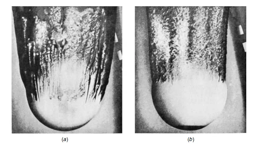
Turbulence may arise either from an increased fluid velocity or from artificial roughening of the forward face of the immersed body. Prandtl roughened the forward face of
a sphere by fixing a hoop to it, with the result that the drag was considerably reduced. Further experiments have been carried out in which sand particles have been stuck to the front face, as shown in Figure 3.3. The tendency for separation, and hence the magnitude of the form drag, are also dependent on the shape of the body.
Conditions of flow relative to a spherical particle are similar to those relative to a cylinder, except that the flow pattern is three-directional. The flow is characterised by the
Reynolds number Re_(= udρ/μ) in which ρ is the density of the fluid, μ is the viscosity of the fluid, d is the diameter of the sphere, and u is the velocity of the fluid relative to
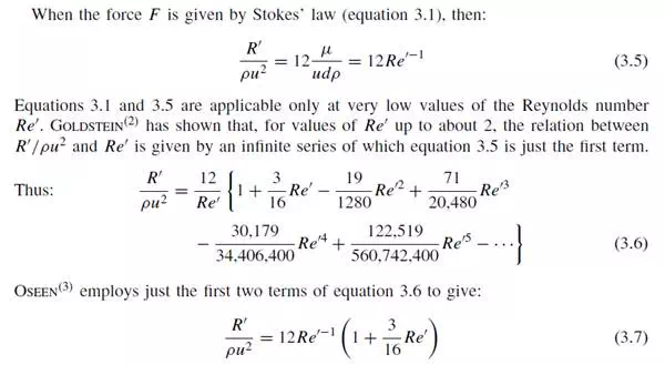
the particle. For the case of creeping flow, that is flow at very low velocities relative to the sphere, the drag force F on the particle was obtained in 1851 by STOKES(1) who solved the hydrodynamic equations of motion, the Navier–Stokes equations, to give:

Equation 3.1, which is known as Stokes’ law is applicable only at very low values of the particle Reynolds number and deviations become progressively greater as
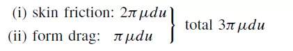
Re_increases. Skin friction constitutes two-thirds of the total drag on the particle as given by equation 3.1. Thus, the total force F is made up of two components:
As Re_ increases, skin friction becomes proportionately less and, at values greater than about 20, flow separation occurs with the formation of vortices in the wake of the sphere. At high Reynolds numbers, the size of the vortices progressively increases until, at values of between 100 and 200, instabilities in the flow give rise to vortex shedding. The effect of these changes in the nature of the flow on the force exerted on the particle is now considered.
THE DRAG FORCE ON A SPHERICAL PARTICLE
Drag coefficients
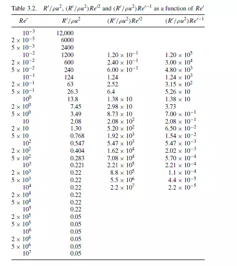
The most satisfactory way of representing the relation between drag force and velocity involves the use of two dimensionless groups, similar to those used for correlating information on the pressure drop for flow of fluids in pipes. The first group is the particle Reynolds number Re_(= udρ/μ).
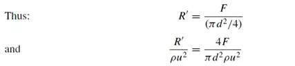
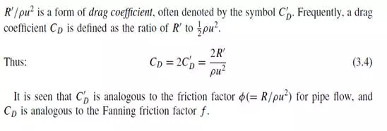
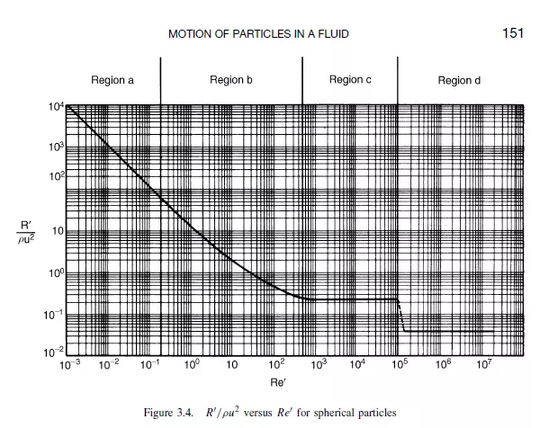
The second is the group R_/ρu2, in which R_ is the force per unit projected area of particle in a plane perpendicular to the direction of motion. For a sphere, the projected
area is that of a circle of the same diameter as the sphere.
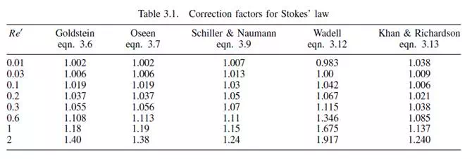
The correction factors for Stokes’ law from both equation 3.6 and equation 3.7 are given in Table 3.1.
It is seen that the correction becomes progressively greater as Re_ increases.
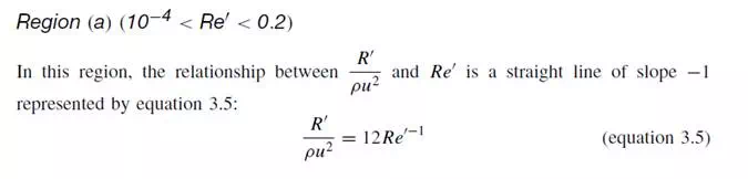
The limit of 10−4 is imposed because reliable experimental measurements have not been made at lower values of Re_, although the equation could be applicable down to
very low values of Re_, provided that the dimensions of the particle are large compared with the mean free path of the fluid molecules so that the fluid behaves as a continuum. The upper limit of Re_ = 0.2 corresponds to the condition where the error arising from the application of Stokes’ law is about 4 per cent. This limit should be reduced if a greater accuracy is required, and it may be raised if a lower level of accuracy is acceptable. Region (b) (0.2 < Re_< 500–1000)
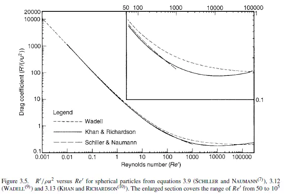
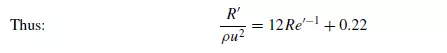
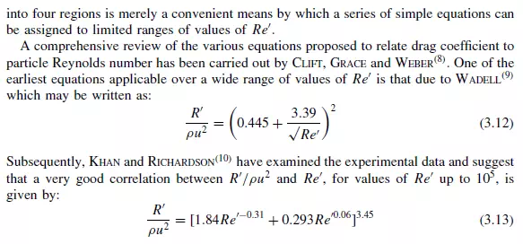
In this region, the slope of the curve changes progressively from −1 to 0 as Re_ increases. Several workers have suggested approximate equations for flow in this intermediate region. DALLAVELLE(6) proposed that R_/ρu2 may be regarded as being composed of two component parts, one due to Stokes’ law and the other, a constant, due to additional non-viscous effects.
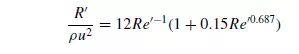
SCHILLER and NAUMANN(7) gave the following simple equation which gives a reasonable approximation for values of Re_ up to about 1000:

Total force on a particle
The force on a spherical particle may be expressed using equations 3.5, 3.9, 3.10 and 3.11 for each of the regions a, b, c and d as follows.