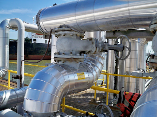
It is well known that chemical process plants located in areas where ambient temperatures can fall well below freezing may require heat tracing of lines and equipment containing process fluids that can freeze or congeal and stop flowing thereby causing costly plant outages and economic losses. In certain cases, freezing of line contents and flow blockage (total or partial) can result in accidents, such as rupture and release of hazardous chemicals from piping or equipment, endangering human life and the surrounding environment.
Well designed heat tracing systems will ensure that the possibility of freezing and blockage is minimized or eliminated. Universally two methods of heat tracing are practiced, electric or steam tracing. In many chemical process plants you will find a combination of both electric and steam tracing depending on the tracing application. In general, both specific application and the economics of electric or steam tracing will govern the choice of heat tracing. The design engineer will have to study both the applicability and the CAPEX / OPEX to decide the type of heat tracing suitable for the given system.
Today’s blog entry specifically deals with heat tracing of using steam. An excel workbook is attached addressing the following:
1. Steam Tracer Sizing Tables: Given the process piping size, the selected tracer material (copper or CS) and the temperature to be maintained in the pipe to prevent freezing, these tables provide the number of tracers, recommended tracer tubing / piping size and the recommended steam flow rates per 100 m of tracer length.
2. Tables for Maximum Tracer length between Traps: These tables provide the maximum length of tracer, at the end of which a steam trap is needed, given the steam flow rate per 100 m of tracer length, and the steam inlet pressure to the tracer.
3. Table for maximum steam flow rate for different steam pressure levels and corresponding steam header size, based on economic pipe sizes, and for steam tracing application.
Spray Tower Scrubber Sizing For Flue Gas Desulfurization
A spray tower sizing web resource is available on the internet which has been used as a basis for the design. However this sizing routine does not provide a clear cut method for determining the gas phase mass transfer coefficient and therein comes the research I had to do to arrive at a empirical method to determine the gas-phase mass transfer coefficient based on a reference document from the EPA (Environmental Protection Agency) of the United States..
The gas-phase mass transfer coefficient KGa has been referred from the second attachment (refer page 37 for the equation). This equation is a direct method to calculate the gas-phase mass transfer compared to the method utilized in the first attachment where this value is obtained in an indirect manner by comparing with an existing spray tower with given dimensions, inlet / outlet SO2 concentrations and lime circulation rate.
If you compare the values of the gas-phase mass transfer coefficient KGa calculated from the indirect method in the first attachment and the empirical equation from the second attachment (EPA report) they are quite close based on a lime circulation rate of 60 m3/h as considered in the first attachment.
Combining the sizing methodology of the first attachment with the gas-phase mass transfer coefficient equation from the second attachment, I have developed an excel workbook which sizes a spray tower. The circulation rate for the limestone solution is considered as 3 liters per actual cubic meter of flue gas which is again referenced from another EPA report. The value of the gas-phase mass transfer coefficient is in turn dependent on the circulation rate through the spray tower. Higher the circulation rate, higher the value of the gas-phase mass transfer coefficient. The reference details are provided in the excel workbook itself.


