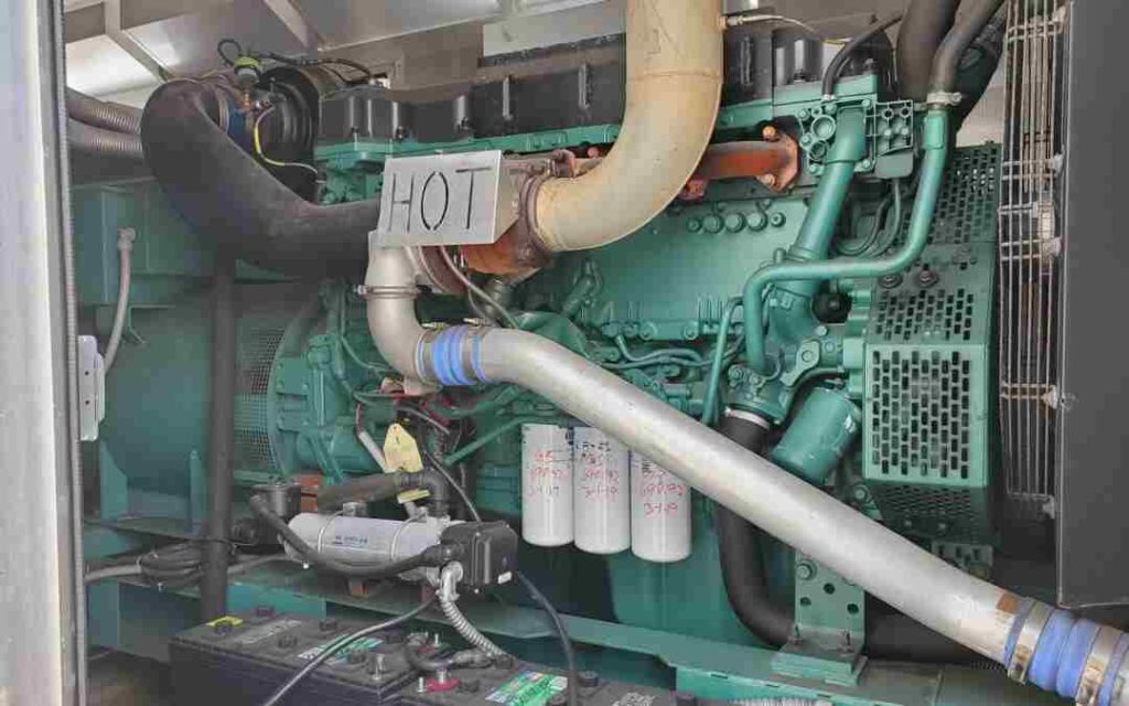
Often process engineers are asked to design a diesel storage and transfer system for diesel engines and diesel power generators. Where to start is often a question among process engineers. There has to be a design basis for designing such a system. Today’s blog entry addresses the design basis for design of a diesel storage and transfer system along with a solved example for such a design. Readers of my blog are welcome to convert this information into an excel spreadsheet calculation and share.

Consider the following calculation example:
Inputs:
No. of Installed DGs: 3
No. of Working DGs: 2
Rating per DG: 1500 kW
Diesel Filling time: 1 hour (to Diesel day tank)
Transfer Pump Design Flow factor: 1.1
Diesel Day tank storage basis: 24 hours
Usable Day tank volume factor = 0.95
Main Diesel Storage Tank hold-up basis = 7 days (Note 1)
Calculations:
Diesel Flow per DG = 0.4 m3/h (from table above with vlookup function)
Total Diesel flow = 0.8 m3/h (0.4*2)
Day tank theoretical capacity per DG = 9.6 m3 (0.4*24)
Day tank working capacity per DG = 10.11 m3 (9.6 / 0.95)
Max. Diesel Consumed per day = 19.2 m3 (9.6*2) where 2 is the no. of working DGs
Max. Diesel Rate = 19.2 m3/h (19.2 / 1) where 1 is the Diesel filling time in hours
Diesel Pump Design Capacity = 21.12 m3/h (19.2*1.1)
Main Diesel Tank working Capacity = 134.4 m3 (19.2*7)
Notes:
1. For on-shore installations the total diesel storage is often considered for 7 days and for off-shore installation it is generally considered as 15 days.
2. The above example calculation considers a separate main storage tank and separate individual day tanks for individual DG sets. In many instances, the individual day tank for DGs may have a hold-up for 8 to 12 hours instead of 24 hours which would require 2 fillings per day for 12 hours hold-up and 3 fillings for 8 hours hold-up


