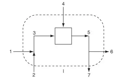
Let’s first examine a multi-unit system composed of a sequential combination of units. Figure 6.3a illustrates a sequential combination of mixing and splitting stages. Streams 1 and 2 combine to form the first mixing point, streams 3 and 4 also combine in the box for the second mixing point, and stream 5 splits (at presumably a pipe junction) into streams 6 and 7. Note that the first mixing point occurs at the combination of streams 1 and 2 (presumably a junction of pipes) while the second mixing occurs where streams 3 and 4 enter the box (presumably representing a process). You will encounter both types of mixing in the problems and examples in this book and in flowsheets in professional practice. Examine Figure 6.3a. Which streams must have the same composition? Do streams 5, 6, and 7 have the same composition? Yes, because streams 6 and 7 flow from a splitter. Do streams 3, 4, and 5 have the same composition? It’s quite unlikely. Stream 5 is some type of average of the compositions of streams 3 and 4 (in the absence of reaction). What is the composition inside the system (the box)? It will have the same composition as stream 5 only if streams 3 and 4 are really well mixed in the subsystem represented by the box.
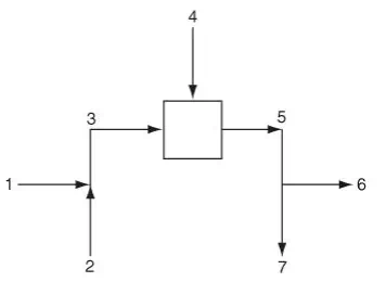
How many material balances can you formulate for the system and subsystems shown in Figure 6.3a? First, let’s examine how many total material balances you can write. You can write an overall total material balance, namely, a total balance on the system that includes all of the three subsystems within the overall system boundary, which is denoted by the dashed line labeled.
In addition, you can make a total balance on each of the three subsystems that make up the overall system, as denoted by the boundaries indicated by the dashed lines II, III, and IV in Figure 6.3c. Finally, you can make a balance about each of the combinations of two subsystems as indicated by the dashed-line boundaries V and VI in Figures 6.3d and 6.3e, respectively.
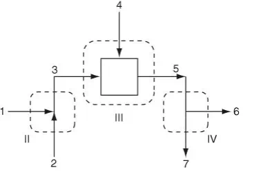
The important question is: How many independent material balance equations can be written for the process illustrated in Figure 6.3a if more than one component exists? In Section 6.1 we stated that you can write one independent equation for each component in each subsystem except for the splitter, for which you can write only one independent material balance equation. For Figure 6.3a, assume that three components are present in each of the separate subsystems shown in Figure 6.3c. You can write three independent material balance equations about the first pipe junction, three for the box, plus one independent equation for the splitter, for a total of seven (7) independent material balance equations.