“Black Box” Analysis: This method of analysis, in the context of process modeling, does not concern itself with how individual process units work. The input and output streams are instead analyzed by applying constraints imposed by nature, namely conservation of mass and conservation of energy. The inner workings of the physical apparatus are not relevant. This course treats process units as black boxes.
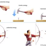
Future courses will go into detail of how different process units work. The First Law of Thermodynamics is a statement of energy conservation. Although energy cannot be created or destroyed, it can be converted from one form to another (for example, internal energy stored in molecular bonds can be converted into kinetic energy; potential energy can be converted to kinetic or to internal energy, etc.).
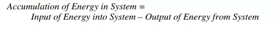
Energy can also be transferred from one point to another, or from one body to a second body. Energy transfer can occur by flow of heat, by transport of mass (transport of mass is otherwise known as convection), or by performance of work. We’ll see examples of these modes of energy transport below. The general energy balance for a process can be expressed in words as:
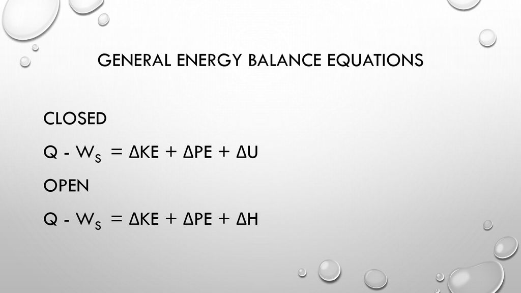
Now the total energy of a system, as considered above, is composed of kinetic, potential, and internal energies. These energies can be transferred into or out of the system by flow of mass through process streams that bring the various forms of energy with them. In addition, they can be transferred by performance of work, or by flow of heat. Equation 6, after expressing all terms as rates, thus becomes:
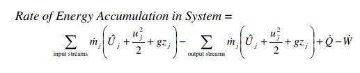
In the first term on the right of equation 7, j runs over all incoming streams, and in the second it runs over all outgoing streams. Note that all terms in equation 7 have units of energy/time. Also, recall the conventions with regard to the sign of the heat and work terms.
Equation 7 can be rewritten in various ways. Let us consider a stationary system (i.e. the system is not experiencing an overall movement in the frame of reference, although its boundary may be deformable). Such a system will in general experience two types of contact work interactions with the surroundings.
The first type of work is called shaft work (symbol: Ws) and arises when a part of the boundary of the system is displaced. Shaft work takes place at moving parts of a system’s boundary across which there is no mass transport. The force is often exerted by some form of machinery. For example, the surface of a rotating impeller exerts force on the fluid (the fluid being the system) as it stirs the fluid, and hence performs shaft work on the “system.” Another example is that of a moving wall, such as a piston. The moving piston exerts force and thus performs shaft work on the contained fluid (the fluid again being the system). A second classification of work that we will encounter is flow work.
Flow work occurs at areas of a system’s boundary across which there is material flowing. The flow work is associated with the force and displacement required to push the material into the system (input streams), or with the force and displacement required to push material out of the system (output streams). A fluid cannot flow unless it creates space for itself when it enters or exits a system. The forces that do the necessary pushing are exerted by particles of the flowing material inside the system on the particles of the material outside the system, and are evaluated at the stream inlets and outlets where the transfer of material into/out of the system takes place. These forces, expressed per area, are the pressure P in the stream