
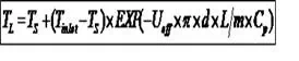
When liquids have to be transported at relatively high temperatures, e.g. viscous crudes/products, temperatures and cooling rates can be determined using the following formulae:
where:
TL = average temperature in cross-section of pipeline at distance L, K
Ts = soil temperature at pipeline depth, K
Tinlet = temperature at pipeline inlet (L = 0), K
Ueff = Effective Heat Transfer Coefficient, W/m2-K
d = pipe internal diameter, m
L = pipeline distance at which TL is to be measured, m
m = mass flow rate of liquid, kg/s
Cp =Specific Heat Capacity of pipeline contents, J/kg-K
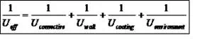
Calculation of Ueff
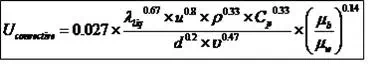
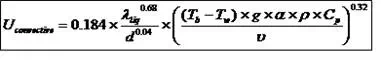
Uconvective
For turbulent flow (Re > 4000)
For Laminar flow (Re < 2300)
where:
Uconvective = Convective heat transfer coefficient, W/m2-K
λliq = liquid thermal conductivity, W/m-K (for crude oil, λliq = 0.13 W/m-K)
u = average liquid velocity, m/s
ρ = liquid density, kg/m3
d = pipe internal diameter, m
Cp = Specific Heat Capacity of pipeline contents, J/kg-K
ν = liquid kinematic viscosity, m2/s
g = acceleration due to gravity = 9.81 m/s2
α = thermal expansion coefficient, 1/K (for crude oil, α = 8*10-4 K-1)
µb = bulk liquid viscosity, Pa.s
μw = liquid viscosity at wall temperature, Pa.s
Tb = bulk temperature, K
Tw = inside wall temperature, K
Notes:
1. The inside wall temp. (Tw) is generally assumed 2-3 degrees lower than the bulk temp. (Tb) in laminar flow
2. The bulk liquid viscosity (μb) and the liquid viscosity at wall temperature (μw) can be assumed same for turbulent flow thus reducing the term (μb / μw) to 1
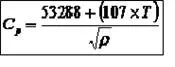
Specific Heat Capacity of Crude Oil
where:
Cp = Specific heat capacity at temperature T, J/kg-K
T = Temperature, ⁰C
ρ = crude oil density at temperature T, kg/m3
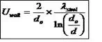
Uwall
where:
Uwall = steel wall heat transfer coefficient, W/m2-K
λsteel = thermal conductivity of steel, W/m-K (for Carbon Steel, λsteel = 52 W/m-K)
do = outside diameter of the steel pipe, m
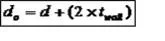
d = pipe internal diameter, m
twall = wall thickness, m
Ucoating (Note: External Coating could be a polyolefin liner or insulation)
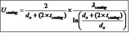
where:
Ucoating = coating heat transfer coefficient, W/m2-K
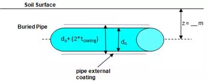
do = outside diameter of the steel pipe, m
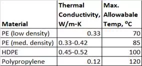
λcoating = thermal conductivity of coating or insulation, W/m-K
tcoating = coating thickness, m
Uenvironment (For Buried pipes the environment is soil)
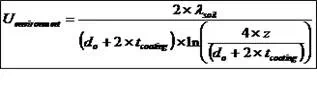
where:
Uenvironment = heat transfer coefficient to the environment (soil), W/m2-K
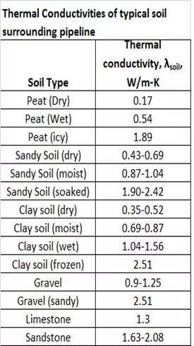
λsoil = thermal conductivity of soil, W/m-K
z = burial depth of the pipe up to the pipe axis, m
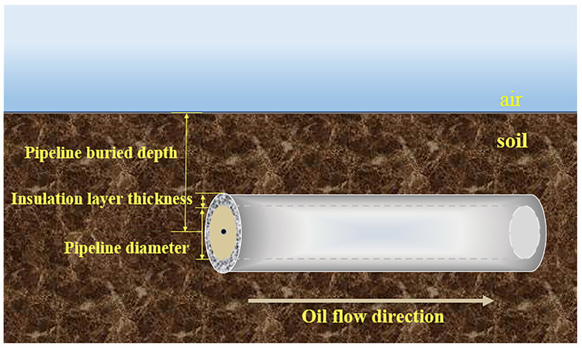
I have developed a spreadsheet for temperature drop in a buried crude oil pipeline based on the above methodology. For a set of conditions that I have used and for a pipeline inlet crude oil temperature of 55⁰C, the temperature drops to 48.5⁰C at a distance of 50 km for a 16 inch NPS pipeline based on the above method. The pipeline is also externally coated.