The feedstock of the platformer is drawn from the refinery”s distillation units. This is first treated by passing the feedstock together with hydrogen over a catayst, in a process called ”hydrotreating, to convert the sulphur and nitrogen compunds to hydrogen sulphide and ammonia, in order to prevent poisoning of the expensive platformer catalyst. After hydrotreating, ,the reactor effluent moves on through a stabiliser column to remove the gases formed (hydrogen sulphide, ammonia and fuel gas). In a second column, the C5 and some of the C6 is removed in a separate fraction called ”tops”. The reason to remove C5/C6 is that this component will crack in the platformer to produce fuel gas, while C6 gets converted into benzene, which can only be allowed in limited amount into the mogas because of its toxicity. From the bottom of the splitter column, the naphtha stream is produced, which is the feed for the Platforming section.
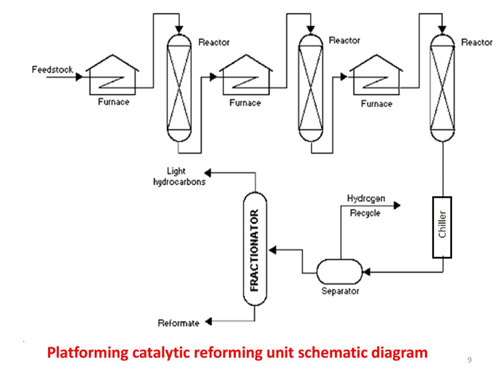
At the heart of the Platformer process are the four reactors, each linked to furnaces to sustain a suffiently high reaction temperature, about 500 0C at the inlet of the reactors.
Description: Platforming Process
Figure 4: The Platforming Process
Over time, coke will build up on the catalyst surface area, which reduces the catalyst activity. The catalyst can be easily regenerated however, by burning the coke off with air. After coke burning, the catalyst needs to be reconditioned by a combined treatment of air and HCl under high temperature. This regeneration step is called ”oxy-chlorination”. After this step the catalyst is dryed with hot nitrogen and subsequently brought in its active condition by reducing the surface with hot hydrogen. The refinery will therefore regulary have to take out one of the reactors to undergo this regeneration process. This type of process is therefore called semi-regen platforming.
During the regeneration process, the refinery will suffer production loss, which is the reason why UOP developed a major process enhancement by making the regeneration possible continuously, in a Continous Catalytic Reformer, CCR. In the CCR unit, the reactors are cleverly stacked, so that the catalyst can flow under gravity. From the bottom of the reactor stack, the ”spent” catalyst is ”lifted” by nitrogen to the top of the regenerator stack. In the regenerator, the above mentioned different steps, coke burning, oxychlorination and drying are done in different sections, segregated via a complex system of valves, purge-flows and screens. From the bottom of the regenerator stack, catalyst is lifted by hydrogen to the top of the reactor stack, in a special area called the reduction zone.
In the reduction zone, the catalyst passes a heat exchanger in which it is heated up against hot feed. Under hot conditions it is brought in contact with hydrogen, which performs a reduction of the catalyst surface, thereby restoring its activity. In such a continuous regeneration process, a constant catalyst activity can be maintained without unit shutdown for a typical runlength of 3 – 6 years. After 300 – 400 cycles of reactionegeneration, the surface area of the catalyst will have dropped to a level (120 – 130 m2/g) that it becomes more difficult to maintain catalyst activity and at such a time normally the catalyst will be replaced by a fresh batch. The batch of ”spent” catalyst is then sent for platinum reclaim to recover the valuable precious metals.
For economic reasons, the design capacities of Platformer units vary from 1000 – 4500 t/d; operating pressures can vary over a wide range, units with from 3.5 barg up to 30 barg can be found, whereby the latest generation CCR”s are typically at the lower pressure range. A lower pressure enhances the endothermic reactions, which gives less cracking reactions and thereby a higher liquid yield. However, at a lower reactor operating pressure, the hydrogen partial pressure will be lower as well, which favours coke formation. The reason why semi regen platformers will not operate at a too low pressure, otherwise the cycle length between regenerations becomes to short. A second disadvantage of operating at a lower pressure is that a larger compressor will be required to boost the pressure of the hydrogen up to the normal pressure of the hydrogen system (about 20 barg). Typical design reformate octane numbers are in the 95-104 range. The reactor temperature is in a region of 450-530 0C.
At the outlet of the last reactor the product is still well above 400 0C. It is cooled down against cold feed in massive heat exchanger, either a so called ”Texas Tower” or a Packinox plate-pack heat exchanger. The special design of those heat exchangers ensures that minimum heat loss occurs in order to minimise the fuel consumption of the furnaces. After passing the feed/effluent exchanger, the reaction products are cooled in air/water coolers and routed to a product separator, where the hydrogen is the main gaseous product. Part of the hydrogen produced is recycled back (via a compressor) to the feed, in order to maintain a high enough hydrogen partial pressure in the reactors. The remainder of the gases are compressed and brought in contact again with the liquid from the product separator. This is step is called ”recontacting” and is done in order to recover as much as possible hydrocarbons from the hydrogen produced. The reactor product, now in liquid form, goes on to the platformer stabiliser which removes Liquid Petroleum Gas ( LPG) and other gases to leave a liquid high octane gasoline component called platformate, ready for blending into the refinery mogas pool. Summarising, the Platformer unit produces about 85% liquid platformate, 10% hydrogen and 5% LPG.
The Continuous Catalytic Reforming unit or better known as CCR Platformer is licensed by UOP, Universal Oil Products, based in USA. More recently, other technology vendors have copied the concept, one of the main competitors for UOP in this field is IFP from France. A CCR typically contains a feed/effluent heat exchanger (Texas Tower or Packinox), 4 furnaces, 4 reactors, a regenerator, overhead recontacting section, net gas compressor, recycle gas compressor and a stabiliser column.